Arrester lightning protection device of industrial surge protector
The classification of the genus: lightning series > arrester lightning protection device of industrial surge protector
Number: 925-1
Specifications: MCR-PLUGTRAB
Type: Industrial surge protector
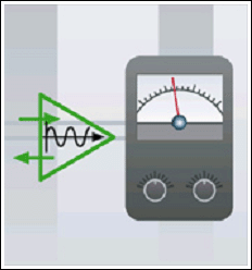
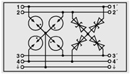
Signal type common in need of protection
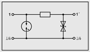
A two-wire switch signal measurement of common reference level
In the use of binary signals (such as locator shared signal) case, according to the position of the switch, the voltage is converted into the distance to another signal line. The reference potential of the voltage is usually depends on the controller, can float to work, can also be non floating operation. Transient voltage surge between the signal line and a reference potential must be limited to the acceptable level.
Schematic diagram of this kind of protection circuit are as follows:
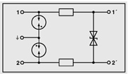
Measurement of two-wire system simulation
Here, we refer to the signal circuit is not a common reference potential and other signal circuit. One of the most commonly used one is 0 (4) -20 mA current loop. The need to measure the physical value is converted to a current value. Can be predicted from the coupled transient surge voltage mainly is symmetrical, which produce between the signal line and related. So the voltage limiting element must be installed between the signal line.
Schematic diagram of this kind of protection circuit are as follows:
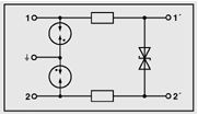
Three wire analog measurement
As with the PT100 thermal resistance temperature measurement can be used for three wire measurement, the current passes through the two signal line flow overheating resistance, third lines for the measurement of pressure drop.
Input transient surge voltage between any core will endanger measurement sensor. This means that you must install protective element in between all the core line, the voltage to the minimum.
Schematic diagram of this kind of protection circuit are as follows:
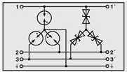
Four wire analog measurement
Measurement on the four line of the case, and make the current through the two lines through the sensor, the other two lines measuring pressure drop, for example, PT100 thermal resistance measurement circuit. In the sensor for directly measuring high resistance voltage means that power does not affect the measurement results on the feeder.
Input transient surge voltage between any core will endanger measurement sensor. This means that you must install protective element in between all the core line, the voltage to the minimum.
Schematic diagram of this kind of protection circuit are as follows:
Intrinsically safe circuit (explosion-proof)
Surge voltage protection device used in intrinsically safe circuit required to meet special requirements. Must comply with international standards, such as EN DIN 50020 / EN 50020 / VDE 0170 / 0171 Part 7:1996-04; DIN VDE 0165 and TRbF 100. The insulation between the intrinsically safe circuit and grounding parts or shell must be AC test voltage tolerance 500Vrms.
Schematic diagram of this kind of protection circuit are as follows:
In the process of signal / factory automation products, according to the line of protection and places of use of different, divided into three types of products, its naming rules are as follows:
Mainly for instrument installation more dispersed flow, pressure, liquid level, temperature signal condition, and often to maintain and update the occasion: products are expressed as MCR-PLUGTRAB = Measurement/ Control/ and Regulation/ -Pluggable/ measurement control regulation of pluggable +TRAB/ surge absorption, is simplified to the model PT-XXX-XXX
The main control room for the measurement and control system of the side lines is relatively large, space is relatively narrow occasions: the products expressed as: TERMITRAB = Terminal/ terminal type +TRAB/ surge absorption, is simplified to the model TT-XXX-XXX
The main control room for the measurement and control system of the side lines is relatively large, space is relatively small, and there is a high maintenance requirements, need to plug the occasion: products are expressed as COMTRAB=COM/ (multi) channel +TRAB/ surge absorption, and is divided into:
CT10... =10 channel integrated protector.
CT8... =8 channel integrated protector.
CTM-XX=COM+TRAB+Modul: combined channel protector.
Signal description should use pluggable type protective conductor number
Current loop 0 (4) -20mA process measurement
Level / flow measurement (suitable for long-distance transmission) PT 2X2-24DC-ST and BE 2 on
PT 1X2-24DC-ST and BE 1 on
CT-2PE... With the CT-TERMIBLOCK terminal 8 or 10 pairs of rows
TT-2-PE-... 1 of the
Can CT... 2PE... With standard distribution frame (free stripping) 8 or 10 pairs of
Level measurement can be PT 2X2... 2 of the
0-10 voltage signals (for short distance transmission) CT... 2PE... With the CT-TERMIBLOCK terminal 8 or 10 pairs of rows
TT-2-PE-... 1 of the
Can CT... 2PE... With standard distribution frame (free stripping) 8 or 10 pairs of
The trip signal (on / off signal) PT 4X1... With PT 4X1-BE (base) 4 line +GND
CT... 2/2... With the CT-TERMIBLOCK terminal row 16 wire or 20 wire
TT-2/2-... Line 2
Can CT... 2/2... With standard distribution frame (free stripping) 16 wire or 20 wire
PT 4X1... With PT 4X1+F-BE 4 line +GND
CT10-18... +F/PE... With CT-TERMIBLOCK (terminal row) 18 line +GND
TT-2/2-... +UBK 2... Line 2
Can CT10-18... +F/PE... With standard distribution frame (free stripping) 18 line +GND
The 24 volt control signal PT100 temperature measurement technology, PT 4... With PT 4-BE 4 line
Intrinsic safety circuit with the Ex flag level / explosion-proof products tank level measurement can be PT2xEX (I) -24DC-ST and BE 2 on
TT-EX (I) 1 on the
PT100 temperature measurement technology PT 4-EX (I) -24DC-ST and BE line 4
PT 4X1...
Technical parameters of 5DC 12DC 12AC 24DC 24AC 48DC
IEC class /VDE specification level: C1, C2, C3, D1
Lightning protection device setting voltage Uc: 6V/4V 13V/9V 18V/13V 28V/20V 40V/28V 53V/37V
Discharge (10/350) s: 2.5kA 2.5kA 2.5kA 2.5kA 2.5kA 2.5kA
Rated current /IN /40 C: 300mA 300mA 300mA 300mA 300mA degree 300mA
Nominal discharge current In (8/20) s: line - line / line - -/10kA -/10kA -/10kA -/10kA -/10kA -/10kA
Maximum discharge current Imax (8/20) s: line - 20kA 20kA 20kA 20kA 20kA 20kA
Impulse voltage (1kV/ s): line line,
Line - < 10V < 18V < 25V < 40V < 55V < 70V
Protection voltage (In): line line,
Line - < 10V < 18V < 25V < 40V < 55V < 70V
The response time of TA (NS): line line / line - to - / - / - / 1 or less than 1 = 1 = 1 = 1 - / - / - / less than or equal to 1
Each road impedance: 4.7 ohm 1-2/5-6 4.7 Omega 4.7 Omega 4.7 Omega 4.7 Omega 4.7 Omega
7-8/11-12 4.7 Omega 4.7 Omega 4.7 Omega 4.7 Omega 4.7 Omega 4.7 Omega
The temperature range of -40 DEG C: to +85
Flame retardant grade, conforming to UL94: V0
Protection level, conforming to IEC 60529/EN 60 529: IP 20
Certification:
Inspection standard: IEC 61643-21:2000-09, E VDE 0845 part 3-1:1999-07
有共用参考电平的二线制开关信号测量
在采用二进制开关信号(例如定位器共用的信号)的情况下,根据开关位置,电压被转换到远处其它信号线。该电压通常取决于控制器的参考电位,可以浮地工作,也可以非浮地工作。信号线和参考电位之间的瞬态浪涌电压必须被限制到可接受的水平。
该类保护电路的原理图如下:
 二线制模拟量测量
这里,我们是指和其它信号电路没有共用参考电位的信号电路。其中最常用的一个是0(4)-20 mA 电流回路。需要测量的物理值被转化成电流值。可以预见来自瞬态浪涌电压的耦合主要是对称的,即产生在相关的信号线之间。因此电压限制元件必须被安装在信号线之间。
该类保护电路的原理图如下:
如用PT100 热电阻测量温度时可使用三线测量,电流经两条信号线流过热电阻,第三条线用于测量压降。
任何芯线之间的瞬态浪涌电压都会危及测量传感器的输入侧。这意味着必须在所有芯线之间安装保护元件,将该电压限制到最小。
该类保护电路的原理图如下:
在四线测量的情况下,使电流经两条线流过传感器,另外两条线测量压降,例如,PT100 热电阻测量回路。在传感器上直接测量高阻电压意味着馈线上的功耗不会影响测量结果。
任何芯线之间的瞬态浪涌电压都会危及测量传感器的输入侧。这意味着必须在所有芯线之间安装保护元件,将该电压限制到最小。
该类保护电路的原理图如下:
用在本质安全电路中的浪涌电压保护装置需符合特殊要求。必须遵守国际标准,例如EN 50 020 / DIN EN 50 020 / VDE 0170 / 0171 Part 7:1996-04 ; DIN VDE 0165 和TRbF 100。本安型电路与接地的部件或外壳之间的绝缘必须能够耐受500Vrms 的交流试验电压。
该类保护电路的原理图如下:
- 主要针对仪表安装点比较分散情况下的流量、压力、液位、温度信号,并经常更新维护场合:产品表述为MCR-PLUGTRAB = Measurement/测量Control/控制and Regulation/调节-Pluggable/可插拨+TRAB/浪涌吸收,简化为型号PT-XXX-XXX
- 主要针对测控系统的控制室侧,线路相对较多,空间也相对狭小的场合:产品表述为:TERMITRAB = Terminal/端子式+TRAB/浪涌吸收,简化为型号TT-XXX-XXX
- 主要针对测控系统的控制室侧,线路相对较多,空间也相对狭小的,并有维护要求高,需要插拔的场合:产品表述为COMTRAB=COM/(多)通道的+TRAB/浪涌吸收,又分为:
- CT10…=10通道集成式保护器。
- CT8…=8通道集成式保护器。
- CTM-XX=COM+TRAB+Modul:可组合式通道保护器。
|
信号描述
|
|
|
|
|
|
|
|
|
|
|
|
|
|
|
|
|
|
|
|
|
|
|
|
|
|
|
|
|
|
|
|
|
(适合短距离传输)
|
|
CT…2PE…带CT-TERMIBLOCK端子排
|
8对或10对
|
|
|
TT-2-PE-…
|
1对
|
|
可
|
CT…2PE…带标准配线架(免剥线)
|
8对或10对
|
|
行程信号等(开/关信号)
|
可
|
PT 4X1…带PT 4X1-BE(基座)
|
4线+GND
|
|
CT…2/2…带CT-TERMIBLOCK端子排
|
16线或20线
|
|
|
TT-2/2-…
|
2线
|
|
可
|
CT…2/2…带标准配线架(免剥线)
|
16线或20线
|
|
PT 4X1…带PT 4X1+F-BE
|
4线+GND
|
|
CT10-18…+F/PE…带CT-TERMIBLOCK(端子排)
|
18线+GND
|
|
|
TT-2/2-…+UBK 2…
|
2线
|
|
可
|
CT10-18…+F/PE…带标准配线架(免剥线)
|
18线+GND
|
|
24伏测控信号
|
PT100温度测量技术
|
可
|
PT 4…带PT 4-BE
|
4线
|
|
本征安全电路带Ex标志防爆产品
|
罐体中液位/电平测量
|
可
|
PT2xEX(I) -24DC-ST和BE
|
2对
|
|
|
TT-EX(I)
|
1对
|
|
PT100温度测量技术
|
可
|
PT 4-EX(I)-24DC-ST和BE
|
4线
|
|
技术参数
|
5DC |
12DC |
12AC |
24DC |
24AC |
48DC |
|
IEC类别/VDE 规格等级:
|
C1,C2,C3,D1 |
|
|
6V/4V |
13V/9V |
18V/13V |
28V/20V |
40V/28V |
53V/37V |
|
泄流量(10/350)µs:
|
2.5kA |
2.5kA |
2.5kA |
2.5kA |
2.5kA |
2.5kA |
|
额定电流/IN /40ºC:
|
300mA |
300mA |
300mA |
300mA |
300mA |
300mA |
|
额定放电电流In(8/20)µs: 线-线/线-地
|
-/10kA |
-/10kA |
-/10kA |
-/10kA |
-/10kA |
-/10kA |
|
最大放电电流Imax(8/20)µs: 线-地
|
20kA |
20kA |
20kA |
20kA |
20kA |
20kA |
|
冲击电压(1kV/µs): 线-线
|
- |
- |
- |
- |
- |
- |
|
线-地
|
≤10V |
≤18V |
≤25V |
≤40V |
≤55V |
≤70V |
|
保护电压(In):线-线
|
- |
- |
- |
- |
- |
- |
|
线-地
|
≤10V |
≤18V |
≤25V |
≤40V |
≤55V |
≤70V |
|
响应时间ta(ns) : 线-线/线-地
|
-/≤1 |
-/≤1 |
-/≤1 |
-/≤1 |
-/≤1 |
-/≤1 |
|
每路阻抗: 1-2/5-6
|
4.7Ω |
4.7Ω |
4.7Ω |
4.7Ω |
4.7Ω |
4.7Ω |
|
7-8/11-12
|
4.7Ω |
4.7Ω |
4.7Ω |
4.7Ω |
4.7Ω |
4.7Ω |
|
温度范围:
|
-40 ℃ to +85 ℃ |
|
阻燃等级,符合UL94:
|
V0 |
|
保护等级,符合IEC 60529/EN 60 529:
|
IP 20 |
|
认证:
|
|
|
|
|
|
|
|
检验标准:
|
IEC 61643-21:2000-09,E VDE 0845 part 3-1:1999-07 |