Watchdog post boundary on column NKZW20F - 12 kv switch circuit breaker OEM/ODM, NKZW20F - 24 kv
Distribution network watchdog dividing line circuit breaker in 10 kV feeder aerial application can greatly reduce the trouble-free lines on the road of collateral forced outage, narrowing the scope of failure blackout, shorten the blackout time users, so as to improve the power supply reliability of the user.
Along with the rapid development of power grid, the safety reliability of power supply demand is higher and higher, in view of the weak links in operation of the grid electricity production department to take effective control measures, doing everything possible to reduce one thousand forced outage, narrowing the scope of power. 10 kV feeder overhead line, due to the open-air set up, its safe operation directly affected by the surrounding environment and climate conditions, high accident rate, accident find difficulties, poor safety and reliability problems. Some overhead line longer remote mountainous areas of users, is often affected by the bad weather can't normal use electricity. Dividing line circuit breaker is the circuit breaker and microcomputer protection measurement and control, and communications module integrated device, with the stem erect, small volume, less investment, the application of it to improve the safety and reliability of the overhead line, is of great significance to ensure the safe operation of power grid.
1. 10 kV feeder features of overhead line
For far and near suburb power supply company, cooperate the webmaster system of 10 kV feeder for the safety of the power supply is very important. However, 10 kV feeder circuit is characterized by structural diversity, accidents, especially in the ChengJin suburbs and outer suburbs areas there are a lot of overhead transmission lines, the overhead transmission lines are often more branch line, the safety and reliability is poor, meet the wind rain and bad weather, frequent ground and short circuit fault, seriously affected the grid safe and reliable power supply.
1.1 line structure complex accident find difficult
Users in line with only one or two side, some lines are T meet multiple feeder or more transformer radiated; Some short circuit to dozens of meters, some lines dozens of kilometers long; Some overhead line in the mountains maintenance difficulties, some distribution transformer aging serious; Some broad overhead, have a plenty of hybrid cable overhead line; Some temporary with overhead line cable users, with a temporary change. Overhead line in case of troubleshooting is difficult, especially when the single-phase grounding line, due to the fault point is difficult to determine, often delay the processing of the accident, caused by failure to expand, and further development for short circuit, or damage to the electrical equipment.
1.2 line protection configuration is relatively simple
10 kV overhead line transformer substation protection configuration flow only commonly, quick break, reclosing protection, in the small resistance grounding system configuration two period of zero sequence protection. Therefore, in order to guarantee the selectivity and sensitivity of relay protection, we must make the whole route in the protection scope, require a failure in the end of the line, protect be sensitive enough. This will across the board due to a malfunction, power outage, and circuit protection are higher and lower JieTiXing cooperate with each other, in the end of the line has no protection, differential time can only lose selective fault tripping and led off the brake.
1.3 different 10 kV grounding method
For arc suppression coil grounded system, 10 kV distribution line when the single-phase grounding fault line tripping, only send ground signal. For the small resistance grounding system, 10 kV power distribution line configuration zero sequence protection, when single-phase earth fault tripping.
1.4 overhead line 10 kV feeder high failure rate, poor reliability, 10 kV feeder high failure rate, poor reliability.
As the user requirements for safety reliability of power supply is more and more high, equipped with microcomputer protection measurement and control, and communications module integrated switch boundary between users and become one of the effective method to solve the problem of the distribution network.
2. The boundary between the performance of the circuit breaker and the main role
2.1 performance and structure
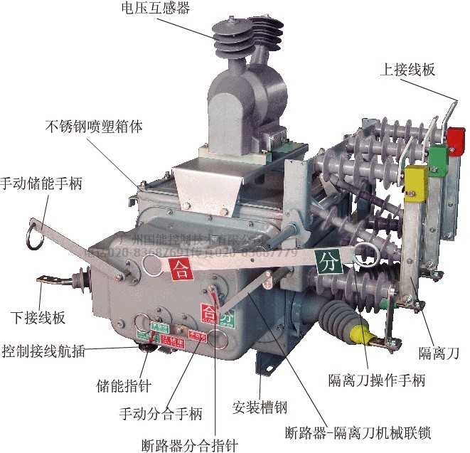
General boundary circuit breaker by the switch body and see most of the measurement and control unit, structure diagram 1.
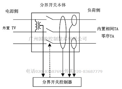
Figure 1 boundary schematic circuit breaker controller
I division circuit breaker a company's main functions: automatically disconnect the user side interphase short circuit faults in the operation, automatic removal of the user side grounding fault, and can be used to disconnect the fault current operation.
Dividing line circuit breaker with a set of external voltage transformer, a set of built-in current transformer; The CPU internal processor and communication module; With voltage during fault tripping judgment and fault memory; Have trip latch function.
Dividing line circuit breaker is applicable to 10 kV neutral point grounding, approved by arc suppression coil grounding or the low resistance grounding system of 10 kV overhead distribution lines with the user (including temporary users) boundary.
2.2 the main function
2.2.1 automatic removal of single-phase grounding fault
When the user side of single-phase grounding fault occurs, dividing line switch automatic brake, dump the fault feeder, ensure substation and feeder on other branches of the safe operation of the user.
2.2.2 automatically disconnect interphase short circuit fault
When the user side interphase short circuit fault occurs, dividing line circuit breaker break-brake dump fault line immediately. Fault line isolation, make the other branches on the feeder users quickly restore power.
2.2.3 quickly locate fault point
User feeder switch, the boundary between failure only user power responsibility, and can take the initiative to report the fault information, make the electric power company can quickly clear the accident point, timely on-site processing, make the fault line as soon as possible to restore power.
2.2.4 monitor user load
Dividing line circuit breaker testing data can be transmitted power management center, achieve real-time monitoring of distant load.
2.3 line circuit breaker fault handling
Dividing line circuit breaker fault handling methods shown in table 2.
Table 2 line circuit breaker fault handling
|
|
|
fault protection treatment
故障点保护处理
|
|
The single-phase grounding fault
|
Non-ground neutral system user limits
中性点不接地系统用户界内
|
single-phase earth fault judgement for permanent ground immediately after trip
判定为永久接地后立即跳闸
|
Neutral point via arc suppression coil grounding user limits
中性点经消弧线圈接地用户界内
|
Neutral point via small resistance grounding user limits
中性点经小电阻接地用户界内
|
Before the substation tripping protection action
先于变电站保护动作跳闸
|
Non-ground system users out
中性点不接地系统用户界外
|
|
Neutral point via arc suppression coil grounded out by the user
中性点经消弧线圈接地用户界外
|
Neutral point via small resistance grounding out by the user
中性点经小电阻接地用户界外
|
|
Interphase short circuit fault
|
User limits brake fault
用户界内故障
|
|
The user out fault
用户界外故障
|
|
3 line circuit breaker fixed value and substation protection setting for coordination with the problem
3.1 for the neutral point grounding or via arc suppression coil grounded system
Interphase short circuit current action constant value: action time limit should be made to match the substation for the action time of the reclosing protection, transient fault protection after the automatic user side, quick disconnect overlap to restore power. Due to the Beijing area 10 kV feeder protection reclosing whole as 1 s commonly, can choose 0.3 ~ 0.5 s.
Single-phase grounding current action constant value: the zero sequence current fixed value, according to overhead line cross section and length, escape routes should be considered for capacitive current. Due to the neutral point grounding or via arc suppression coil grounding system, the single-phase grounding fault happens, transformer substation line protection tripping, signal grounding, only allowed to run short indirectly. In order to judge fault, and the boundary of circuit breaker action time, should consider to avoid the instant grounding deadline, and action again after substation grounding signal trip, can choose 6 ~ 8 s.
3.2 for the neutral point via small resistance grounding system
Interphase short circuit current action constant value: same as above.
Single-phase grounding current action constant value: neutral point via small resistance grounding system, due to the transformer substation of 10 kV overhead line general configuration, two pieces of zero sequence protection for a period of 120 a, time limit of 0.2 s; Two 20 a, time limit for 1 s. Therefore, while dividing line circuit breaker of the zero sequence current fixed value and action time, should be made to match the substation zero sequence protection, 0 s.
In 4 line circuit breaker running and maintenance problems should be paid attention to
Appearance should be regularly check line circuit breaker ontology and controller are in good condition; Dividing line circuit breaker state indicating whether it is right, whether running state energy storage; Porcelain crack, damage; Dividing line circuit breaker lead spacing is in accordance with the code requirements; Each part connection fastening, do you have any overheating phenomenon; Lightning arrester is in good condition; Grounding device in good condition, do you have any rust; Controller lights flashing warning.
Check whether the line circuit breaker is rotating or grounding resistance measuring whether extended, dividing line circuit breaker users in internal equipment installed and trouble-free, after the success of the substation feeder circuit breaker tripping overlap, should be timely organization find line fault points, found brake line circuit breaker points, should be timely reported to the administrative departments of electric (dividing line circuit breaker, the controller failure indicator continue flashing 48 h).
Should be checked regularly arrange for clearing dividing line circuit breaker, the inspection period and circuit board rod inspection cycle is the same. In principle dividing line circuit breaker operation more than 10 years should schedule rotation maintenance.
5 line circuit breaker installation problems should be paid attention to
Dividing line circuit breaker device can only be installed on the branch line or the end of the line, shall not be used string, as shown in figure 2.
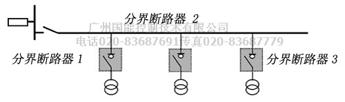
Figure 2 line circuit breaker installation schematic diagram
Dividing line circuit breaker as the boundary between power companies and users first circuit breaker, the general installation in 10 kV overhead distribution lines feeder first tree stem, lateral load by the user.
When users into line for overhead line, separating the load side of the circuit breaker with suspension insulator suspension overhead insulated wire is introduced into, the user first fundamental pole power supply side insulated wire installed earth wire hanging ring, keep unipolar isolating switch.
When users into line for cable line, from the boundary between the load side of the circuit breaker with suspension insulator suspension overhead insulated wire leads to the user the first fundamental pole, the connecting cable directly. Users in the first part pole ring side insulated wire installed hanging earthing wire of power, no longer drop fuse installation, retain unipolar isolating switch.
Installed line circuit breaker ontology, relevant departments should organize before insulation resistance testing, and power frequency withstand voltage test and test; Insulation resistance measurement standards: use 2500 V wave measuring insulation resistance by megger, dividing line circuit breaker, relatively and fracture Ω 1000 M or higher. Power frequency withstand voltage test standard: dividing line circuit breaker, relatively and fracture: 42 kV, 1 min. Dividing line circuit breaker closing operation surface and instructions should be toward the outside.
Dividing line of the circuit breaker controller installation: controller of installation height should not be less than 2.5 m, the switch control cable (with attachments) controller controller end plug into the controller panel jack, the other end insert boundary dedicated socket circuit breaker base, plug should be tighten. Control cable rope body end, bend and straight segment every 1 m should use 2.5 was fixed, single strands of copper core insulation wire twist plait five laps. Cable should be horizontal flat vertical, should not be skew.
6 the conclusion
Dividing line circuit breaker application in the 10 kV overhead lines on the road, greatly reduces the trouble-free line joint forced outage, narrowing the scope of failure blackout, shorten the blackout time users, thereby improving the user power supply reliability.
Dividing line circuit breaker better solve the interphase short circuit occurred 10 kV substation, and quickly locate fault point when single-phase earth fault.
Technical features: NK - ZW20F - 12/24 type outdoor ac high voltage vacuum circuit breaker is a boundary between user line switch.
Mainly by ZW20F - 12 type vacuum circuit breaker ontology, NKR - 02 fault detection controller and external voltage transformer of three parts
Three by air and outdoor seal control cable for electrical socket connection, with functions of fault detection and protection control function and communication function
Can reliable judgment, detection limits and the zero sequence current and marginality milliamperes interphase short circuit fault current, and realize automatic removal of single-phase grounding fault and short-circuit fault
Ontology switch is vacuum arcing and adopts SF6 gas insulated, cabinet adopted the introduction of Japanese Toshiba gas seal, explosion-proof, insulation structure technology
Overall sealing performance is good, internal filling the SF6 gas leakage, is not affected by the external environment,
The spring operating mechanism for the miniaturization and performance optimization design of action reliability is several times higher than domestic traditional spring mechanism
The axis of the main loop and the contact between the adduction of the chain structure, the main circuit of small contact resistance, low temperature rise.
Product performance and reliable is a real free maintenance products.
Second, the product is mainly in accordance with the following national standards:
Switch parts: GB1984 the high voltage circuit breaker
GB/T11022-1999 "standard of high voltage switch equipment control and common technical conditions"
Control terminal parts: GB/T726-2000 "relay basic test method and device"
GB/T17626-1998 "electromagnetic compatibility test and measurement technology electrical transient bursts immunity test"
Three, use of environmental conditions
1, the ambient air temperature: - 40 ℃ ~ + 40 ℃; Temperature differences: daily temperature variation is not more than 25 ℃; According to the nature of SF6 gas material, when the environment temperature to 40 ℃, such as the chamber pressure is 0.05 Mpa, at this time still for gas SF6, guarantee the normal work of the product. (when the environment temperature 40 ℃, gauge pressure is 0.05 Mpa, SF6 liquefaction point for - 55 ℃; zero pressure table, SF6 liquefaction point not more than 60 ℃).
2, the wind speed is not more than 35 m/s;
3, no inflammable, explosive danger, strong chemical corrosion (such as all kinds of acid, alkali or smoke, etc.) and the place of violent vibration.
4, altitude, 1000 m or less;
5, cover thickness: 10 mm;
6, air polluted degree: level IV;
7, seismic intensity: 7 degrees or less;
8, power network neutral point grounding way: neutral point grounding, neutral point via arc suppression coil grounding, neutral point by the low resistance grounding.
Four, the main technical parameters
4.1 the circuit breaker rated parameters are shown in table 1
|
REF序号
|
Project 项 目
|
Unit单 位
|
Values 数 值
|
|
1
|
rated voltage 额定电压
|
KV
|
12
|
|
2
|
rated frequency 额定频率
|
Hz
|
50
|
|
3
|
rated current 额定电流
|
A
|
630
|
|
4
|
rated short circuit breaking current 额定短路开断电流
|
KA
|
20
|
|
5
|
rated current peak tolerance (peak)
额定峰值耐受电流(峰值)
|
KA
|
50
|
|
6
|
rated short-time resistance current (4S)
额定短时耐受电流
|
KA
|
20
|
|
7
|
rated short circuit close current (peak)
额定短路关合电流(峰值)
|
KA
|
50
|
|
8
|
mechanical life times 机械寿命次数
|
times
|
10000
|
|
9
|
rated short-time open circuit current open circuit number 额定短时开断电流开断次数
|
|
30
|
|
10
|
power frequency withstand voltage (1min):dry tried (ground / fracture )
|
KV
|
42/48
|
|
11
|
lightning impulse withstand voltage (peak)relative/fracture 雷电冲击耐受电压(峰值)相间、相对/断口
|
KV
|
75/85
|
|
12
|
the rated operating sequence points 额定操作顺序
|
|
Off-0.3s-OnOff-180s-OnOff
|
|
13
|
AC220 auxiliary circuit of rated voltage V rated operating voltage 额定操作电压辅助回路额定电压
|
V
|
AC220
|
Note: when using ground elevation of more than 1000 m, resistant to high voltage should be in accordance with GB/T11022-1999 revised accordingly.
4.2 circuit breaker assembly adjusting parameters are shown in table 2
|
REF序号
|
Project 项目
|
Unit 单 位
|
Values数 值
|
|
1
|
contact open from 触头开距
|
mm
|
9+1-0.5
|
|
2
|
contact over travel 触头超行程
|
mm
|
3+1-0.5
|
|
3
|
the average brake speed 平均分闸速度
|
m/s
|
1.2±0.2
|
|
4
|
average closing speed 平均合闸速度
|
m/s
|
0.6±0.2
|
|
5
|
contact bounce time ms closing 触头合闸弹跳时间
|
ms
|
≤2
|
|
6
|
the casing interelectrode center distance
箱体内极间中心距离
|
mm
|
135±1.5
|
|
7
|
outside enclosure interelectrode center distance 箱体外极间中心距离
|
mm
|
280±2
|
|
8
|
three-phase break-brake synchronism time 三相分闸同期性时差
|
ms
|
≤2
|
|
9
|
per pole circuit dc resistance 每极回路直流电阻
|
µΩ
|
≤200
|
|
10
|
closing time 合闸时间
|
ms
|
≤45
|
|
11
|
brake time 分闸时间
|
ms
|
≤45
|
|
12
|
dynamic contact allowed to wear the thickness 动触头允许磨损厚度
|
mm
|
3
|
|
13
|
when closing contact pressure 合闸时触头压力
|
N
|
2000±200
|
|
14
|
the SF6 gas pressure rated pressure (table) SF6气体额定压力(表压)
|
MPa
|
“0”
|
|
15
|
net weight 净重
|
Kg
|
185
|
4.3 operator main technical parameters
4.3.1, energy-storage motor: dc series motor, its technical data such as table 3
Type bs YJ220-5301 rated voltage (ac 220 v) normal working range (85% ~ 120% rated voltage)
Rated power (20 w) energy storage time under rated voltage (5 s or higher)
4.3.2, hand machine operating force: the institution with the maximum operating force of energy storage handle less than 25 kg.
4.3.3, closing electromagnet: the solenoid electromagnet, the coil technical data such as table 4.
Rated voltage (ac 220 v) rated current (3.9 A) rated power (860 w) 20 ℃ when the coil resistance (56 Ω)
Normal working voltage range (65% ~ 110% rated voltage)
4.3.4 break-brake electromagnet coil parameters,
Rated voltage (220 v dc) rated current (3.9 A) rated power (860 w) 20 ℃ when the coil resistance (56 Ω)
Normal working voltage range (65% ~ 110% rated voltage)
4.4
Current transformer in the circuit breaker in the body of A and C in each configuration 1 only current transformer, variable than 400/5, and used for protection.
4.5 the zero sequence current transformer
In the circuit breaker this configuration 1 zero sequence current transformer, variable than 20/1, 0.1 ~ 5 a section in the zero sequence current, has a good linear relationship, under the rated load (0.1 VA) strain ratio error less than 3%, when the zero sequence current is 400 a, the secondary output current is not less than 5 a.
4.6, power supply operation
4.6.1 circuit breaker working need to manipulate the supply. Irfpa operating current can be ac or dc 220 v power supply, but is in commonly 10 kv line on the external power supply transformer or voltage transformer operation, in order to obtain ac 220 v power supply operation, 1 kva capacity, weight 45 kg.
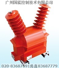
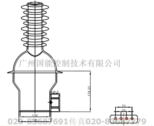
JDZW - 10 r outdoor epoxy pouring silicone rubber compound insulation voltage transformer
J -- -- -- -- -- -- -- -- -- -- -- -- -- - voltage transformer
D -- -- -- -- -- -- -- -- -- -- -- -- single phase
Z -- -- -- -- -- -- -- -- -- -- - epoxy pouring
W -- -- -- -- -- -- -- -- outdoor installation
10 - rated voltage (kV)
R - with high voltage side of the fuse
Creepage distance is 580 mm
4.7 controller parameters are shown in table 5
|
REF
|
Project项 目
|
Unit 单 位
|
Values参 数
|
|
1
|
the input voltage 输入工作电压
|
V
|
AC220
|
|
2
|
input voltage frequency 输入工作电压频率
|
HZ
|
50
|
|
3
|
input voltage allowed range
输入工作电压允许波动范围
|
%
|
±20
|
|
4
|
the machine power consumption 整机功耗
|
W
|
<10
|
|
5
|
second sampling phase current input values 采样相二次电流输入值
|
A
|
0~9
|
|
6
|
sampling zero sequence current input value 采样零序一次电流输入值
|
0~4
|
|
7
|
power input value sampling error 电量输入值采样误差
|
%
|
±5
|
|
8
|
over-current protection secondary current setting range 过流保护二次电流整定范围
|
A
|
0.8~9 可调
|
|
9
|
quick break protection secondary current adjustable setting range 速断保护二次电流整定范围
|
1.0~9 可调
|
|
10
|
over-current protection action value 过流保护动作延时时间值
|
ms
|
200~5000 可调
|
|
11
|
zero sequence pilot protection current setting range 零序保护一次电流整定范围
|
A
|
0.2~4 可调
|
|
12
|
zero sequence protection action delay time value 零序保护动作延时时间值
|
S
|
0.2~1200 可调
|
|
13
|
Number of reclosing times 重合闸次数
|
次
|
1~3
|
|
14
|
reclosing time for the first time
第一次重合时间
|
S
|
0.3~10
|
|
15
|
simple remote control distance
简单遥控器距离
|
米
|
100
|
|
16
|
Net weight 控制器净重
|
kg
|
12
|
Fifth, the basic structure of the circuit breaker ontology
5.1 the breaker ontology structure as shown in figure 1
Circuit breaker ontology structure by the conductive loop, insulation system, seal and shell (as shown in figure 1), its appearance is shown in figure 2. Conductive loop outlet and inlet line of the conductive rod, conductive clip, soft links connected to the vacuum arcing chamber. This product adopts the SF6 gas insulated. Into the wire insulation casing by using epoxy resin and silicone rubber integral casting, to reduce the volume switch, A, C two phase using the corner casing, ensure good external insulation; Internal adopts composite insulation structure, in the case of not filled with SF6 gas, also can achieve the insulation of the corresponding level. This product USES mature seal structure. Cover and shell cover is made of stamping forming groove seal, pointer to the output shaft adopts double "O" ring seal, into the wire casing integral casting, ensure good air tightness.
5.2 operating mechanism This product operation mechanism for electric energy storage, power points, both hand machine, manual points, close brake springs, the whole structure system, the closing coil, manual switching systems, auxiliary beginning and storage instructions and other parts (as shown in figure 4, figure 5)
Figure 1 circuit breaker internal structure diagram
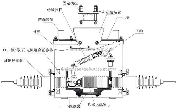
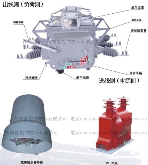
Figure 2 figure shape
Six, the working principle of the circuit breaker of the ontology
6.1 energy storage
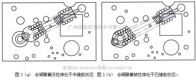
Energy storage is shown in figure 3, figure 3 (a) for closing spring energy storage state, in figure 3 (b) for the closing spring has energy storage condition.
6.1.1 electric energy storage principle: motor output torque acting on the body of the pinion, the chain of transmission to the main shaft of big sprocket, thus turn arm rotates, the closing spring energy storage, when the screw press the switch on the turn arm, cut off the motor power, spring energy storage.
6.1.2 hand machine principle: the actuator output shaft by hand machine, small gear will be rotating torque on the output shaft is passed to the pinion, big full of meshing gears (on the main shaft, and with big sprocket rivet), thus turning arm rotates, the closing spring energy storage.
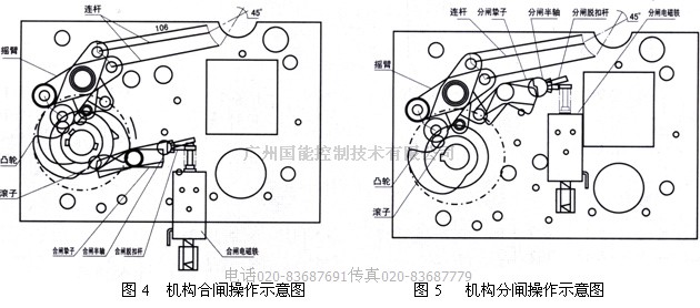
6.2 closing figure 4 closing operation schematic diagram for your organization.
6.2.1 electric switching: agency received after switching signal, closing electromagnet moving core upward movement, push the switch tripping lever upward movement, make the closing half shaft counterclockwise, lifted to perform the first quantum constraints; At the same time, closing main quantum oppressed by the roller and rotate counterclockwise, remove energy storage to maintain, located on the main shaft CAM for the release of the closing spring produce wallop, hitting hand machine axis (i.e., output shaft) rocker arm, through the connecting rod drive to switch, so as to complete the closing operation.
6.2.2 manual: pull the switch manually handle, exert (about 80 ~ 80 n) force drives the closing pull plug on the half shaft rotates counterclockwise, drive along the counterclockwise closing half shaft, to produce the same effect as the closing electromagnet operation.
6.2.3 reclosing operation: after the agency to release the energy of the energy storage spring, to complete the closing operation; In closing state, agency for energy storage operation, the complete energy storage operation, the institutions in the closing has energy storage state; In this state once received the right signal, can realize automatic reclosing operation at a time.
Figure 6.3 gate 5 for institutional break-brake operations
6.3.1 electric brake: mechanism after receiving points brake signal, break-brake electromagnet moving core upward movement, promoting break-brake tripping lever upward movement, counterclockwise, break-brake half axis of break-brake main quantum constraints. Break-brake zhi son, meanwhile, oppressed by the roller and rotate counterclockwise, rocker arm as part of the brake in the switch spring driven and counterclockwise, so as to complete the closing operation.
6.3.2 break-brake: manually pull brake manually handle, exert (about 80 ~ 80 n) force driving break-brake pull plug on the half shaft rotates counterclockwise, along the counterclockwise drive break-brake half shaft, which produce the same effect with break-brake electromagnet operation.
6.4 electric operating mechanism secondary control circuit schematic diagram in figure 6, when the agency in the storage at the end of the state, travel switch WD normally closed contacts connected, M motor drive the closing spring began to energy storage, energy storage, after the completion of travel switch WD normally closed contacts disconnect, cut off power supply, motor stalling. After the closing spring energy storage, agency if at break-brake position, normally closed contacts auxiliary switch S1 connected, as long as there is switching signal, closing electromagnet HQ electricity, electric switch. Electric switch over, auxiliary switch
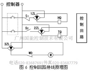
Normally closed contacts S1 disconnect, cut off the closing electromagnet power supply. WD normally closed contacts through M energy-storage motor power, motor M drive the closing spring energy storage, until completion of the storage, travel switch WD normally closed contacts disconnect again.
Switch after closing, auxiliary switch is normally open contacts closed S2, as long as there is brake signal, TQ break-brake electromagnet coil is electrified, break-brake operations. Break-brake, auxiliary switch open normally open contacts S2, cut off the break-brake electromagnet coil power supply.
Seven, control and protection devices
In order to obtain excellent protection performance, product adopted the NKR - 02 type controller. Users can be in situ for points on the controller parameter setting, closing operation, also can use the PDA to the controller parameter setting, refer to, by closing operation and protection setting refer to various events recorded, or by specifying a cell phone in the form of text messages instead of PDA. In addition, you can use simple wireless remote control and close operation of circuit breaker.
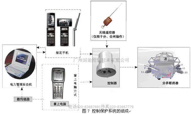
NKZW20F - 12 / T630 - type 16 boundary between outdoor ac high voltage circuit breaker control and protection systems as shown in figure 7. The power management background machine for the user should bring along their own equipment. If not, does not affect the use of dividing line circuit breaker.
Simple wireless remote control for the effective control of radius of 30 meters, and can only carry on the circuit breaker points, closing operation. Simple wireless remote control for special. Special simple wireless remote control and the controller is one to one, its advantage is when a boundary between a circuit breaker operation, won't cause other separation circuit breaker points, by mistake. Figure 7 for the control of protection system of physical figure. From figure 7, you can see that person and NKR - 02 type controller, the interface between the PDA or mobile phone short message way may be used. These two approaches. PDA method has the advantage that you can easily control, but its effective service radius of 30 meters, use mobile phone text messages and controller interface, as long as the dividing line circuit breaker with the personnel of the communication signal is good, for there is no limit to the distance, but the dividing line circuit breaker installation site communication signals must be good. And we have to pay for mobile phone short message service. Users must be comprehensive consideration, and then choose any kind of interface.
7.1 the controller
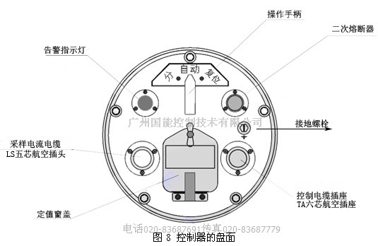
7.1.1 disk
The bottom of the controller is the disk, as shown in figure 8.
7.1.2 setting window
After setting window open, that is, visible setting window pane.
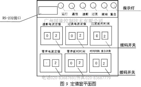
7.1.3 controller fixed value setting
Users can by dividing line circuit breaker control device setting window to fixed value setting below:
And over-current protection setting value, the delay time; Interphase short circuit quick break protection fixed value; Zero sequence protection setting (single-phase grounding current and zero sequence protection delay time; Overlap, reclosing time.
7.1.3.1 zero sequence current setting value size: related to the parameters of the lateral line dividing line circuit breaker load (line length, overhead lines and cable line), can choose according to the following table:
Zero sequence protection fixed value setting principle recommended list
|
Switch the load side length of overhead lines开关负荷侧架空线长度(m)
|
<1000
|
<4000
|
|
|
|
|
|
|
|
|
|
Lateral load switch cable length 开关负荷侧电缆长度(m)
|
|
50
|
100
|
150
|
200
|
250
|
300
|
350
|
400
|
450
|
|
Constant value定值(A)
|
0.2
|
0.4
|
0.6
|
0.8
|
1.0
|
1.2
|
1.4
|
1.6
|
1.8
|
2.0
|
|
Lateral load switch cable length 开关负荷侧电缆长度(m)
|
480
|
500
|
550
|
600
|
650
|
700
|
750
|
800
|
850
|
900
|
|
Constant value定值(A)
|
2.2
|
2.4
|
2.6
|
2.8
|
3.0
|
3.2
|
3.4
|
3.6
|
3.8
|
4.0
|
If you don't use the recommended value in the table, the user can also adopt the following calculation formula of zero sequence current setting value is calculated.
Fixed value calculation formula

Recommend 7.1.3.2 zero sequence protection delay time constant value principle
Neutral point grounding system, or by the arc suppression coil grounding whole as the 60 s, neutral point by the low resistance grounding for 30 s. Also can be set according to the actual circumstance of circuit system.
Recommended: according to the operation experience of zero sequence current protection setting value 4 a file 20, zero sequence protection delay constant value 600 s' 29
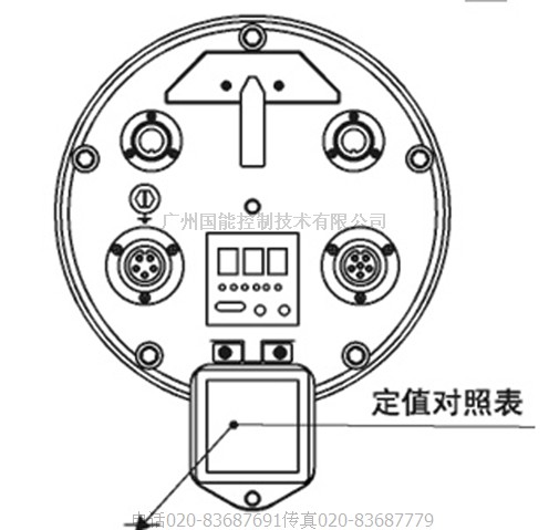
7.1.4 fixed value table
Setting window open, can see on the fixed value window cover with a fixed value table and controller display definition table. The set values for the fixed value table clearly show value corresponds to dial the code switch to the actual setting value. By changing the setting value dial the code switch, can be set or modified flow current setting value, quick break current setting value, the flow time delay time, zero sequence current protection setting value and zero sequence protection time and number of coincidence and overlap time protection setting value. Regardless of whether or not there is electricity controller, can change the dial the code switch value, to set or modify the setting value. If the dial the code switch setting is equal to the largest dial code gear of fixed value table, controller will be effected according to the maximum value gear. If you want to setting value is greater than the set value table, please contact the manufacturer.
NKR - 02 watchdog dividing line circuit breaker controller dial the code setting value table
|
code 拨码
|
quick break 速断二次A
|
over load secondary current 过流二次A
|
over load time 过流时间S
|
zero current(primary side current) 零序一次A
|
zero current time零序时间S
|
reclose times重合次数
|
reclosing time重合时间S
|
|
00
|
退出
|
退出
|
0.0
|
退出
|
0.0
|
退出
|
0.3
|
|
01
|
2.0
|
0.8
|
0.2
|
0.2A
|
0.2s
|
1次
|
0.5
|
|
02
|
2.5
|
1.5
|
0.4
|
0.4A
|
0.4s
|
2次
|
1
|
|
03
|
3.0
|
2.0
|
0.6
|
0.6A
|
0.6s
|
3次
|
2
|
|
04
|
3.5
|
2.5
|
0.8
|
0.8A
|
0.8s
|
3次
|
3
|
|
05
|
4.0
|
3.0
|
1.0
|
1.0A
|
1.0s
|
3次
|
4
|
|
06
|
4.5
|
3.5
|
1.2
|
1.2A
|
1.2s
|
3次
|
5
|
|
07
|
5.0
|
4.0
|
1.4
|
1.4A
|
1.4s
|
3次
|
6
|
|
08
|
5.5
|
4.5
|
1.6
|
1.6A
|
1.6s
|
3次
|
7
|
|
09
|
6.0
|
5.0
|
1.8
|
1.8A
|
1.8s
|
3次
|
10
|
|
10
|
6.5
|
5.5
|
2.0
|
2.0A
|
2s
|
|
|
|
11
|
7.0
|
6.0
|
2.2
|
2.5A
|
3s
|
|
|
|
12
|
7.5
|
6.5
|
2.4
|
3.0A
|
4s
|
|
|
|
13
|
8.0
|
7.0
|
2.6
|
3.5A
|
5s
|
|
|
|
14
|
8.5
|
7.5
|
2.8
|
4.0A
|
6s
|
|
|
|
15
|
9.0
|
8.0
|
3.0
|
4.5A
|
7s
|
|
|
|
16
|
9.5
|
8.5
|
3.2
|
5.0A
|
8s
|
|
|
|
17
|
10
|
9.0
|
3.4
|
5.5A
|
9s
|
|
|
|
18
|
11
|
9.5
|
3.6
|
6.0A
|
10s
|
|
|
|
19
|
12
|
10
|
3.8
|
6.5A
|
15s
|
|
|
|
20
|
13
|
10.5
|
4.0
|
7.0A
|
20s
|
|
|
|
21
|
14
|
11
|
4.2
|
8.0A
|
30s
|
|
|
|
22
|
15
|
11.5
|
4.4
|
9.0A
|
40s
|
|
|
|
23
|
16
|
12
|
4.6
|
10 A
|
50s
|
|
|
|
24
|
17
|
12.5
|
4.8
|
11 A
|
60s
|
|
|
|
25
|
18
|
13
|
5.0
|
12 A
|
120s
|
|
|
|
26
|
19
|
14
|
|
13 A
|
240s
|
|
|
|
27
|
20
|
15
|
|
14 A
|
360s
|
|
|
|
28
|
21
|
16
|
|
15 A
|
480s
|
|
|
|
29
|
22
|
17
|
|
20 A
|
600s
|
|
|
7.2 handheld computers
PDA or PDA with data query, query, modify, setting value, remote operation, state of query, modify password pair, background processing and equipment, and other functions.
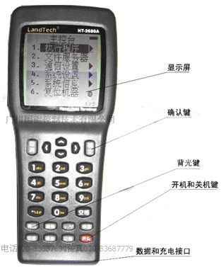
To the operation of the controller can also be done through high-end wireless handheld PDA, palmtop, USES the high-grade CPU, built-in real-time multitasking system. Display intuitive, easy to learn. Palmtop has the protection function.
On/off
1 press the switch on/off button, PDA start self-checking, 0.5 seconds later, boot self-checking. Appeared after the boot screen, as shown.
2 in normal operation, press the switch on/off the phone, can turn it off;
3 in the normal operation, if the user does not have more than 20 minutes for any keyboard operation, will automatically be turned off.
[backlight key]
Where the environment is dark when using, can press the key, open the backlight, press [backlight key] again, backlit shut down. PDA initialization complete, first asks the user to enter the password, the password to factory default set to 12345, after the user lose the password, it will directly to the main menu.
7.3 PDA features introduced search equipment after entering the main menu, the user should first click on the menu] [search equipment, can be found near the remote control device, and returns the device number, equipment if the search is less than, perhaps because too far away, or point of view is wrong, the user can search again after the move distance, if there are more than two devices at the same time, near requires the user to use] [manual input, to enter the corresponding number. The device number range is: 1-65000. (switch device number is consistent with the small remote control number).
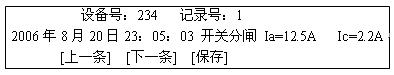
[query record] when switch or circuit events, dividing line switch controller can record up to 30 recent events recorded, and can record in memory, records can be saved 10 years, the use of [query record] can query the controller inside the event log, the record number is 0, said recent events, record number is 1, said the events of the last record of 2, said to the last event and so on. When the record is full, and when a new event, is the oldest one record will be overwritten. When check records, if this record needs to be saved, the user can press the [save] key and save it, returning home by background processing function, will save the records to the computer for processing.
A typical event record format, for example, as follows:
[control]
After entering/remote control, screen display:

[remote break-brake] : brake switch points
Closing/remote control switch: switch
/ change the password, you can modify the palm computer boot password, enter/change the password after the first asks the user to input the five new password, enter your new password request again, if two input correctly, then change the password is successful, the new password can be used.
[use] simple introduce the basic operation flow of the PDA, users in the use of palmtop, can refer to the instructions.
[device reset] when circuit failure occurs, the controller on the pillars of fault indicator will light up, when the line back to normal, requires the user to manually switch to] [manual reset handle position, the malfunction indicator lamp can be reset, the handheld device reset function, can also be distant fault indicator light will be reset.
[modified fixed value] after entering modified fixed value, PDA display the following picture:
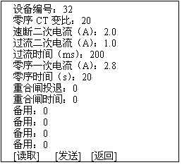
/ modify the fixed value, the first [reads] fixed value, the existing fixed value of [reads] to based on modified [reads] constant value at the end of can't modify directly.
Send [] : send modified fixed value to divide switch controller, if the modification is successful, PDA will return tips, but if there is no success, PDA will also prompt the user.
Meditation, which need to modify the value, can be directly meet the point.
"Equipment serial number" the serial number of the controller, range: 1-65000.
"Zero sequence CT changes than" switch inside the boundary between zero sequence CT changes than wear heart, factory has prepared the user does not have to change, otherwise it will affect the zero sequence protection.
"Quick break protection current fixed value when the line current exceeds the set value, the switch action immediately, isolate the fault zone.
"Over-current protection current fixed value when the line current exceeds the set value and achieve over-current protection delay time, the switch action isolation fault zone.
A "zero sequence current setting value" when the line more than fixed value of zero sequence current and zero sequence protection delay time, switching isolation fault zone.
"Exit dial code fixed value" when the setting value is 0, above dial the code switch controller panel set up effective, the user can't through the PDA is modified; When the set value is 1, above dial the code switch controller panel setting, all the fixed value can only be set by PDA.
"LCD adjustment" when the temperature changes, the liquid crystal display (LCD) may be lighter or darker, the user can be adjusted through the menu, so you can see the LCD.
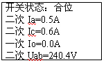
"Reclosing retreat" 0-1 - exit reclosing in reclosing state [query] after entering state [query], screen display:
[return]
"Second Ia, Ic" said: after transformer, input to the controller of the secondary current.
"Io" : it means the data is a side of zero sequence current switch.
"Secondary Uab" : it means the voltage transformer secondary side voltage.
Background processing is used to processing preserved in palmtop, in the event log. In the main menu [background processing], screen display the following three functions:
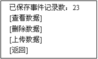
[view]
View is saved in the palmtop, in the event log
/ delete data will be stored in the event of palmtop, record all deleted
/ upload data will be stored in the palmtop, in the event log on the cable to the desktop computer, so that the user further processing.
Upload the data, the first to use the data will be connected to the serial port of the PDA and desktop computer, and then click computer [to] - [all programs] - [attachment] - [communications] - [super terminal], and then click [properties], the baud rate is set to: 9600 stop bit: one data bits: 8 bits of data flow control: OFF/ON, and then open the serial port, then click ON PDA "upload data" button above, it can be stored in the event of palmtop revelation to the desktop computer. Super terminal Settings, close the Windows.
Pair] [equipment used to check the function division of switch controller system time to the event log when the time is accurate.
Input time format: year - month - day: points: seconds after input the correct time, press the send button, complete the pair. No data returned for fashion. After the pair, the user can by pressing [reads] key to check whether the pair is correct, if not correct, need to operate for fashion.
Operational considerations:
1, wireless PDA to should take put down gently, when used in the process of using or carrying, be careful be affected with damp be affected with damp and collision, avoid damaged antenna.
2, watch the rain.
3, in the process of operation, unstable if there is a screen or some screen, or deviate from the very serious, please restart after shutdown. Note: the user if you don't do anything more than 20 minutes, PDA will automatically power off.
7.4 mobile phone short message interface (the machine without this feature)
7.4.1 SMS communication services
Short message service is one of the GSM system provides GSM terminal (mobile phone), through a service center for text information transceiver application services, including service center to complete the information store and forward capability. And because the GSM network has realized the networking and roaming across the country, has the characteristics of network capacity. Users need other networking, at the same time greatly improve network coverage for clients to save the expensive cost and maintenance cost, to overcome the traditional private network communication system of large investment cost, high maintenance, network monitoring coverage is narrow and limited number of users to some defects. Compared with traditional cluster system, GSM network in wireless network coverage has incomparable advantage, combined with the GSM itself have a two-way data transfer function, makes the application rapidly. Therefore, our company developed a controller which has the function of GSM SMS communication fault detection. The controller can edit commands in the form of text messages, you can easily to parameter setting, remote control switch points, such as query, query the event log switch states. And the controller can also be through the way of SMS communication and power management center backstage machine to join.
7.4.2 SMS code
Using a mobile phone short message to controller parameter setting, refer to, by closing operation and protection setting refer to various events recorded, downward instructions must be controller can identify the code of instructions. Controller can query answering phone, its upward reply, also only is a simple, code information. So the way of using mobile phones, short message code. NKR - 02 rent information between controller and mobile code as shown in the table "NKR - 02 type controller SMS code table"
7.4.3 the matters needing attention when using SMS code
1, write SMS command, must be in English uppercase and lowercase format in Chinese pinyin or English format, SMS command is invalid.
2 for seconds, zero sequence protection action time unit, other time limit of protection operation units in milliseconds.
3, down the fixed value of zero sequence current instruction, the number of input must be an integer, which represents the current one over ten of the integer.
4, with short message communication between controller and, using the mobile phone must be into the China mobile network.
5, a query set value displayed when a quick break and a current value, modify the quick break and a fixed value when the input current setting value, is a current value.
The working principle of the eight, the protection of the controller
8.1 single-phase earth fault movement theory
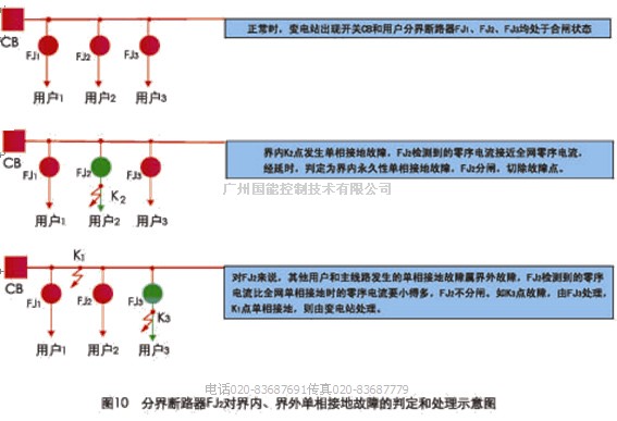
8.1.1 neutral point grounding or neutral through petersen coil grounding system circuit is normal, the dividing line circuit breaker of substation outlet switch are still in the closing state, once the user community in single-phase earth fault occurs, dividing line circuit breaker built-in zero sequence current transformer is detected the zero sequence current is close to the entire network of zero sequence current, more than setting the parameters of the beforehand, by the time delay, judgment for single-phase earth fault in permanent, dividing line circuit breaker automatically brake, to isolate the fault zone. Using mobile phone short message communication, information is also reported to the accident. Other users and main road adjacent single-phase earth fault belong to foul trouble, the circuit breaker zero sequence current transformer is detected the zero sequence current is far less than that of setting value, the circuit breaker is not action. Single-phase earth fault and processing is shown in figure 10.
8.1.2 neutral point via small resistance at the neutral point grounding system through small resistance grounding system, the substation with zero sequence protection, but as long as the user community in single-phase earth fault occurs, the user of the boundary between circuit breaker and substation protection relies on action time to cooperate, dividing line circuit breakers ahead of substation switching action, so as to cut off the single-phase earth fault. Ensure the safety of other users.
In and out of single-phase grounding fault judgement and processing, as shown in figure 10
8.2 interphase fault movement theory
Interphase fault occurs when a user limits, dividing line circuit breaker short circuit current is detected, when the short circuit current exceeds over current setting value, after a delay, after confirmed as permanent fault current, circuit breaker points brake. If the short circuit current exceeds quick break current setting value, the breaker points brake immediately. Circuit breaker fault zone isolation, use mobile phone short message communication, also reported events in SMS way.
Nine, protection treatment
Phase current controller input signal, A total of four: A, C, AB and voltage phase current and zero sequence current.
Controller through real-time monitoring the input quantities, judging and comparing with constant value line fault types, and thus for the corresponding processing. In the table below for the system neutral point of different operation modes protection treatment results. 9.1 single-phase fault handling
System grounding fault point location Protect the handling
|
|
|
fault protection treatment
故障点保护处理
|
|
The single-phase grounding fault
|
Non-ground neutral system user limits
中性点不接地系统用户界内
|
single-phase earth fault judgement for permanent ground immediately after trip
判定为永久接地后立即跳闸
|
Neutral point via arc suppression coil grounding user limits
中性点经消弧线圈接地用户界内
|
Neutral point via small resistance grounding user limits
中性点经小电阻接地用户界内
|
Before the substation tripping protection action
先于变电站保护动作跳闸
|
Non-ground system users out
中性点不接地系统用户界外
|
|
Neutral point via arc suppression coil grounded out by the user
中性点经消弧线圈接地用户界外
|
Neutral point via small resistance grounding out by the user
中性点经小电阻接地用户界外
|
|
Interphase short circuit fault
|
User limits brake fault
用户界内故障
|
|
The user out fault
用户界外故障
|
|
Note: dividing line of switch Settings and substation outlet switch or fixed value to match the time limit switch action at the next higher level.
Ten, installation,
10.1 switch installation of ontology
10.1.1 before installation to check the products before you check whether product nameplate, certificates are in conformity with order, the packing list is consistent with the physical. After confirmed to clear the surface dust, dirt, and then observe the products of normal directions points or whether if casing deformation, etc., and then put on hand machine handle for manual operation points and 5 times first, then 5 times electric points in operation. Mechanical action after normal, 42 kv / 1 min power frequency withstand voltage test. Other experiments according to user's actual situation, selective, such as: voltage, current transformer, polarity and variable ratio test precision. Check after the completion of installation.
10.1.2 product installation process, do not turn, tilt, anti-shock measures and requirements. Horizontal lift when lifting.
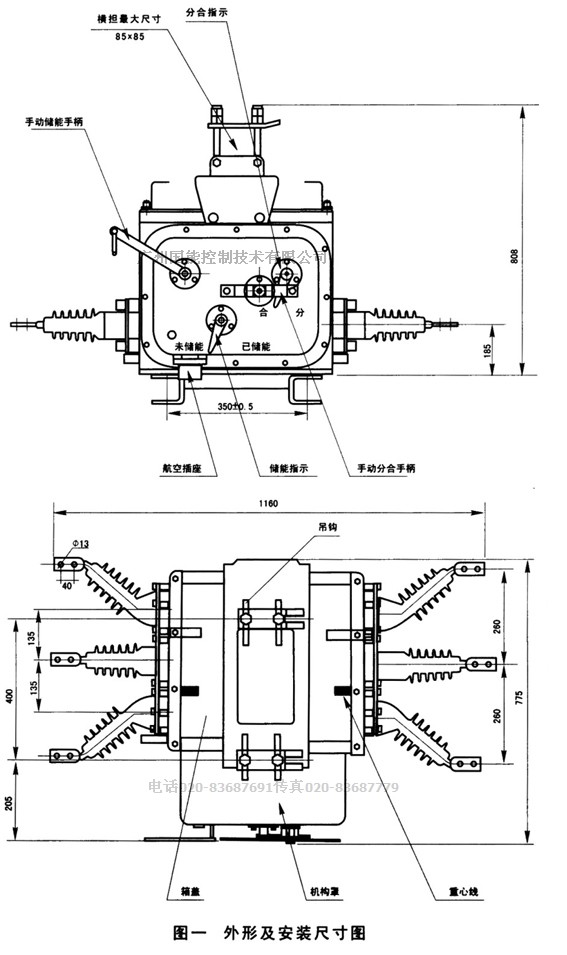
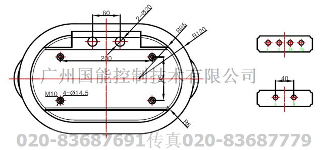
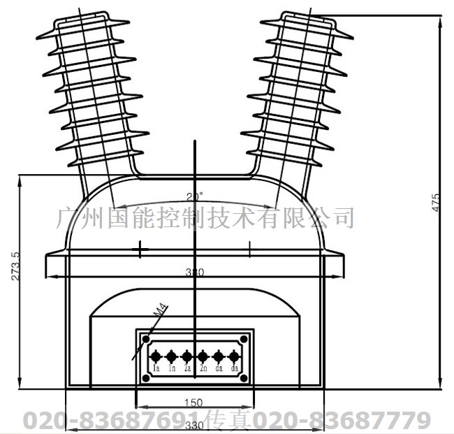
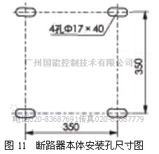
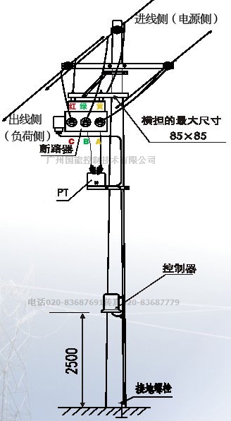
10.1.3 circuit breaker installed with 4 M16 x 50 bolt, the specific installation dimensions as shown in figure 11, installed on the electric pole figure 12 for reference.
The preparing work before installation:
1 hardware processing
Based on the selected installation method processing and installation of hardware and external PT bracket, installation hardware processing size attachment figure in detail.
Ready to install 2 attachments
The following is a single device the required number of attachment:
6 (1) high voltage surge arrester power source side and load side all three)
(2) 10 kv insulator specification and quantity according to the installation and the size of the pole).
3) hoop (specification and quantity according to the installation and the size of the pole).
6 (4) switch wire connecting clamp size according to the wire diameter of the field lines);
5) grounding conductor.
6) PT stents.
3 to install equipment examination
Appearance inspection content:
1) fastening and sealing are in good condition?
2) shell casing and presence of lesions?
3) control the socket and pin are in good condition?
4) handles and share the pointer in the normal position?
Insulation measurement content:
1) insulation resistance: : time for secondary and 10000 mq or higher; Secondary to ground: 10 or more mq
2) high voltage: : time for secondary and 42 kv, 1 min; Secondary to ground: 2 kv, 1 min;
No controller for 42 kV withstand voltage test!
Prohibited under the condition of the controller is connected to the circuit breaker to withstand test!
Prohibited in the case of secondary AC220V plug in to any pressure test!
Installation steps
Step 1: install the circuit breaker bracket, and the bracket of PT
Step 2: lifting
Before lifting switch in break-brake position;
Note:
* hook the hook hook on cord length should be 0.8 m;
* protect switch don't collide in the process of lifting to avoid injury casing and casing;
* switches allow a slightly tilted.
Step 3: fixed
The circuit breaker operation to install than frame level cross arm slightly higher place, place the circuit breaker on the mounting bracket horizontal cross arm, with four sets of M17x60 stainless steel bolt and nut fastening. Determined to fixed well, the lifting cord. The outer type in the lower part of the circuit breaker PT PT rack installation, with four groups of M14x40 stainless steel bolt, nut fastening.
Step 4: a cable connection
1) when a circuit breaker does not need to install the isolation, can clip will divide directly connected to circuit switch sides, if a circuit breaker need to install the isolation, use the copper wire cable terminals are connected to the isolation and outlet side breaker.
2) with two more than about 10 square insulation high-voltage wire a pick up in AB phase of the power supply side, the other side and on the high side terminals of PT.
Note:
* note keep the insulation of the spacing between cable in at least 100 mm; * circuit breaker is not less than 6.5 meters off the ground * PT spacing not less than 1.5 meters and circuit breaker
* please be sure to install lightning arrester in switch on both sides of each phase in case of lightning damage to equipment. * the controller is not less than 2.5 meters off the ground
The installation of the controller
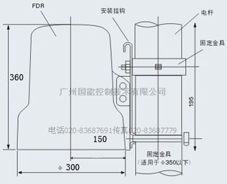
The overall dimensions and installation of the controller
Hardware processing and installation accessories
Controller in the factory "hook" installation has been attached with goods, users only need to prepare the fixed hardware installation, fixed fittings processing according to the different of the installation points is different also. General controller installed on the cylindrical pole, the fixed hardware (cap) according to the diameter of the cylindrical pole to prepare.
Users should bring along their own number of attachments (below is needed for installing a controller).
Size 1, 2 hoop, according to the size of the pole;
2, ground wire, wire diameter not less than 16 was, the length of the line on the basis of on-site installation.
Eleven, product storage and maintenance
11.1 packaged circuit breaker during transportation, loading and unloading, no inversion, strong vibration and impact.
11.2 circuit breaker stored in dry and ventilated, moistureproof, and against corrosion of indoor harmful gas or have covered warehouse, long-term storage should be in the transmission part and butter, and regularly check whether environment meets the requirements.
Product storage of fixed number of year for 15 ~ 20 years.
Prohibited under the condition of circuit breaker or controller charged call waiting controller aviation joint!
It is forbidden to aviation plug and cable bending to more than 45 degree Angle.
Because the controller is precision electronic products, don't have to be grounded!
When ordering 12, the user clear
1, the product model, name, parameters, rated voltage, current, short circuit current and communication;
2, transformer ratio and measuring accuracy grade, protection grade CT technical requirements;
3, number and date of delivery;
4, the names and number of spare parts, spare parts;
5, and other special operation requirements, such as contact, accessories, etc.
6, product certification (including PT, CT, zero sequence current transformer)
7, installation instruction manual;
8, packing list;
9, products, secondary wiring diagram.
10 please indicate the sea dials high, if the sea dials high products
Here is the order table, for example
|
Delivery date供货日期
|
site地点
|
|
The name of the project工程名称
|
Project number工程编号
|
|
The product name产品名称
|
Watchdog dividing line circuit
breakers
看门狗分界断路器
|
|
Product model产品型号
|
NKZW20F-12
|
|
Rated voltage额定电压
|
10KV
|
|
Rated current额定电流
|
630A
|
|
The breaking short circuit current(4 s) 开断短路电流(4S)
|
20KA
|
|
Close short circuit current (4 s) 关合短路电流(4S)
|
50KA
|
|
Operator 操作机构
|
spring弹簧
|
|
Controller operating power 控制器操作电源
|
AC220V by one outdoor PT(10kV/220V)提供
|
|
Shell current transformer phase than壳内电流互感器变比**
|
A C CT400:5 (10P10) Zero N CT20:1
|
|
Circuit breaker shell Iron断路器外壳
|
clad coating
铁壳喷塑
|
|
(PT and switch) cable length PT与开关(2.5平方)电缆长度
|
10m (10米)
|
|
Switch to the controller cable length开关与控制器(1.5平方)电缆长
|
|
|
Either altitude height 海拨高度
|
1km
|
|
Controller shell
控制器外壳
|
SMC cap 塑料帽子
|
|
Controller function 控制器功能
|
reclose quick Break overload Zero protection 重合 过流 速断 零序 保护
|
|
communication 通信方式
|
no 无
|
|
Multi-function remote contro(PDA) 多功能遥控器(掌上机PDA)
|
Yes有
|
|
Small remote control小遥控器
|
Yes 有
|
|
load capacity 负荷容量
|
1000kVA
|
|
Power side with the isolation Switch电源侧带隔离刀
|
no
|
|
Line neutral point grounding way switch 开关所在线路中性点接地方式
|
not grounded 不接地
|
Installation method 1 hoisting under voltage transformer (PT) in a circuit breaker
Controller dimension figure controller built-in installation, 12 kg weight, need a hoop fixed outside (fixed hardware)
Control cable length of seven meters, air connection plug connection
PT 10 mm2 insulated wires used in high pressure side of 10 kv AB, PT and circuit breaker installation distance is about 1.5 meters,
Circuit breaker installed 6.5 meters off the ground
Installation method 2 with the voltage transformer (PT) on the circuit breaker installed (not recommended)