Video monitoring system of transformer fault anti-theft
1, an overview of the current situation is very prominent theft, destruction of power facilities, not only caused a great loss to national property, also influence people's life endanger public safety, influence of Power Grid Corp on social image of high reliability. Theft criminals exploit, booty off hand move quickly, the lack of evidence from the scene, the public security organs is difficult to qualitative, the verdict, which gave the criminals have the advantage.
In order to provide field evidence of theft of electric power facilities in cases of strong, and to rapidly locate the fault equipment, the company developed the anti-theft monitoring system image transformer.
The system can monitoring the operation management area of the transformer, monitoring the transformer malfunction or when the theft, in a timely manner to transformer fault information and photographs of the scene through the GPRS/CDMA/3GTDCDMA wireless network to upload to the monitoring center, at the same time, the information is forwarded to managers of mobile phone.
The monitoring center shows the actual location of the fault point the way to map the fault of transformer, rapid positioning, fault data stored in the database for query, get the information of staff on duty with the police to the scene immediately after the inspection situation, deal with relevant problems.
At the same time, the monitoring center software has strong control function, can query the current state of transformer, historical alarm information, can modify the management of personnel information, route information, monitoring point information etc..
2, characteristics
(1) of the transformer operation monitoring technology is advanced, the operation of on-line monitoring of transformer
(2) video capture theft situation, provide field evidence and powerful, has the deterrent role against theft
(3) failure after tripping, according to the fault current of each terminal, can quickly and accurately locate the fault line section.
(3) the use of existing wireless GPRS/CDMA network, no need to set up communication channels, the use of a wide range of
(4) use of maintenance free battery power, long service life, and low battery alarm function
(5) the master station software is powerful, has a number of management functions, and can be continuously upgraded
(6) and line fault monitoring system uses a set of monitoring center, monitoring range, small investment.
3, the detection principle
1, the normal operation of the transformer will always have the voltage, but also because of its existing distribution transformer loss (copper loss and iron loss), so even if the transformer load have stopped working, the line also always have a smaller current transformer, and after the theft, loss of voltage and current transformer, on the line to the transient process of zero, this is stealing transformer system, specifically, the criterion can be summarized as:
(1) the voltage drop of 0 monitoring points;
(2) the monitoring point current of 0;
At the same time the occurrence of the above 2 conditions, the alarm system will send the alarm signal, alarm management personnel in the confirmation of transformer is not implemented by the management department of the planned power outages, can judge the transformer is stolen, you can quickly inform the public security or security departments, timely arrest.
2, for the transformer does not run the electricity, the use of sets of infrared detection technology, sound, vibration detection technology as one of the module, and sends out the alarm signal in transformer was disassembled, management personnel in affirming alarm transformer is not caused by internal staff, can judge the transformer is stolen.
4, system composition
The system consists of two parts, were installed in the monitoring center (to substation, electric power bureau as a unit) and a transformer site, as shown in figure 1.
(1) the monitoring center part includes:
The system main station software and hardware set, communication switch a
(2) part of the site includes transformer installation:
Transformer anti-theft detector I (containing GSM mobile phone module), or the anti-theft detectors II, GSM module.
自供电高压线路故障指示器
1、产品概述
AWKD系列高压线路故障指示器是安装在110KV及以上的架空线路上,用于检测线路发生接地或短路故障点的装置。一旦线路发生故障,巡线人员可借助指示器上的红色报警显示,迅速确定故障区段,分支及故障点。
产品特点
1. 自供电型(导线自取电):采用特殊材料和核心技术,当导线负荷电流大于10A时即开始取电;当线路负荷大于30A时,正常工作和本地无线通讯完全不用后备锂亚电池的电量。
2. 短路故障判据:采用速断、过流检测法或者自适应负荷电流的过流突变法,适应各种短路、过流和过负荷情况,确保与变电站出口动作一致。可在线灵活设置参数,检测灵敏、可靠。
3. 接地故障判据:捕捉接地瞬间线路杂散电容的首半波尖峰突变电流、线路工频稳态电流和线路对地电场的变化。可在线灵活设置参数,检测灵敏、可靠。
4. 自动复位:1~48h定时复归时间参数(在线可设置),也可通过本地无线遥控翻牌/复归。根据需要可定制抢修故障并恢复送电立即复归的智能复归功能。
5. 带电装卸:采用简易托杯和绝缘操作杆进行带电安装、拆卸。
6. 显示方式:LED发光,翻牌显示。
7. 通信方式:短距离无线通讯,只接收、不发送,主要用于设置参数和遥控复归。
8. 防锈死:压线板采用优质尼龙材料,压线簧为不锈钢,不会与导线“熔”为一体;卡线结构也采用不锈钢导磁材料和防锈工艺设计。
9. 防拒动:动板采用大截面设计,导磁性能好,结合小信号数字采样技术,在出厂前可以改突变电流参数。在农网线路小负荷电流、小突变电流场合也能正确指示,不拒动;在城网线路两相接地短路或者缓慢过流时也能灵敏启动!
10. 防误动:防空载合闸涌流误动;防重合闸期间非故障分支误动!
2、产品分类、型号及安装
根据线路供电方式不同,110KV及以上高压线路故障指示器可分为两种,下表所示
| 名 称 |
线路供电方式 |
型 号 |
安装方向性 |
检测故障 |
| 高压线路 |
单电源供电线路 |
AWKD-OGH-D |
无方向性 |
接地或短路 |
| 故障指示器 |
双电源联网供电线路 |
AWKD-OGH-S |
色标一致朝向同一电源侧 |
接地或短路 |
| 安装位置 |
110KV及以上高压线路上 |
| (安装方法见附页) |

翻牌显示 翻牌发光显示
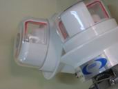
图一、高压线路故障指示器外形图
3、检测原理
AWKD型高压线路故障指示器是110KV及以上线路用来检测接地或短路故障点的装置。它与短路故障指示器的区别在于二者的适用电压不同。同时在安装方向上也有所区别。
对于单电源供电线路,设计原理基本和短路故障指示器相同,不同之处增加了快速检测电路;
对于双电源联网供电线路,其设计原理是基于线路在发生故障时的电流突变和功率方向判断。当短路瞬间电流有突变且大于一定数值并与设定的功率方向相同,而且线路很快因故障而停电,则认为线路上发生了故障,故障指示器动作并翻牌显示。
图二、高压线路故障指示器原理图
4、技术参数
| 适用导线电流 |
适用导线电压 |
动作响应时间 |
静态 |
适用 |
环境 |
动作 |
复位 |
| 功耗 |
导线 |
温度 |
次数 |
时间 |
| ≤1200A |
≥110KV |
≥0.06S |
≤10μw |
≤240mm2 |
-35℃~+65℃ |
3000次 |
标准24、48小时,特殊要求可订作 |
| 引用标准: |
| GB311-83/683 |
GB311、3-1997 |
GB11022-89 |
| 高压试验方法 |
高压输变电设备的绝缘配合 |
高压开关设备通用技术条件 |
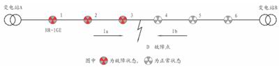
| 安装位置:110KV及以上的高压架空联网供电线路或单电源线路 |
如图,建议在变电站A和变电站B断路器出口处各安装一个指示器,这样就可以检测到整条线路的故障,并且故障点一定在所有翻牌和不翻牌的指示器之间(D点)。考虑到出现短路故障时线路实际的复杂情况,原理上并没有严格界定故障点一侧所有翻牌的指示器具体在哪一侧。