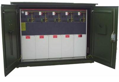
All insulation hermetic SF6 watchdog NKVSR3 OEM/ODM introduction by dividing line switch open and close Tank
Watchdog boundary all insulation hermetic sulfur hexafluoride opening and closing the switch Tank
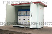
Total box type SF6 sulfur hexafluoride gas full insulation full sealed vacuum switchgear Tank
Distribution network watchdog dividing line switch in 10 kV line application can greatly reduce the trouble-free of line of collateral forced outage, narrowing the scope of failure blackout, shorten the blackout time users, so as to improve the power supply reliability of the user.
Boundary load switch to load switch and microcomputer protection measurement and control, and communications module integrated device, with the power distribution network configuration, small volume, less investment, the application of it to improve the safety and reliability of the distribution network, is of great significance to ensure the safe operation of power grid.
1. The boundary between the performance of the load switch and the main role
1.1 performance and structure
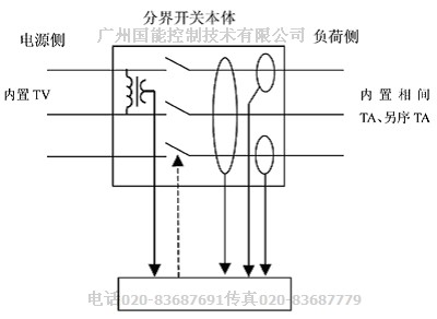
General boundary switch by the switch body and see most of the measurement and control unit, structure diagram 1.
| |
|
fault protection treatment
故障点保护处理
|
|
The single-phase grounding fault单相接地故障
|
Non-ground neutral system user limits
中性点不接地系统用户界内
|
single-phase earth fault judgement for permanent ground immediately after trip
判定为永久接地后立即跳闸
|
Neutral point via arc suppression coil grounding user limits
中性点经消弧线圈接地用户界内
|
Neutral point via small resistance grounding user limits
中性点经小电阻接地用户界内
|
Before the substation tripping protection action
先于变电站保护动作跳闸
|
Non-ground system users out
中性点不接地系统用户界外
|
|
Neutral point via arc suppression coil grounded out by the user
中性点经消弧线圈接地用户界外
|
Neutral point via small resistance grounding out by the user
中性点经小电阻接地用户界外
|
|
Interphase short circuit fault相间短路故障
|
User limits brake fault
用户界内故障
|
Supply side circuit breaker tripping after power failure, demarcation load switch tripping 电源侧断路器跳闸停电后,分界负荷开关分闸
|
The user out fault
用户界外故障
|
|
My company switch between its main functions: automatic isolation in user side interphase short circuit fault, automatic removal of the user side grounding fault, and can be used to close the load current operation.
Boundary load switch with a built-in voltage transformer, a set of built-in current transformer; The CPU internal processor and communication module; With voltage during fault tripping judgment and fault memory; Have trip latch function.
Boundary load switch is applicable to 10 kV neutral point grounding, approved by arc suppression coil grounding or the 10 kV distribution line of low resistance ground system and user (including temporary users) boundary.
2.2 the main function
2.2.1 automatic removal of single-phase grounding fault
When the user side of single-phase grounding fault occurs, dividing line switch automatic brake, dump the fault feeder, ensure substation and feeder on other branches of the safe operation of the user.
2.2.2 short-circuit fault isolation and automatically
When the user side interphase short circuit fault occurs, boundary load switch in substation for protection tripping, break-brake dump fault line immediately. Substation outlet switch after reclosing, fault line isolation, make the other branches on the feeder users quickly restore power.
2.2.3 quickly locate fault point
User feeder switch, the boundary between failure only user power responsibility, and can take the initiative to report the fault information, make the electric power company can quickly clear the accident point, timely on-site processing, make the fault line as soon as possible to restore power.
2.2.4 monitor user load
Boundary load switch testing data can be transmitted power management center, achieve real-time monitoring of distant load.
2.3 boundary load switch fault handling
Boundary load switch fault handling methods are shown in table 2.
Table 2 line circuit breaker fault handling
|
|
|
fault protection treatment
故障点保护处理
|
|
The single-phase grounding fault
|
Non-ground neutral system user limits
中性点不接地系统用户界内
|
single-phase earth fault judgement for permanent ground immediately after trip
判定为永久接地后立即跳闸
|
Neutral point via arc suppression coil grounding user limits
中性点经消弧线圈接地用户界内
|
Neutral point via small resistance grounding user limits
中性点经小电阻接地用户界内
|
Before the substation tripping protection action
先于变电站保护动作跳闸
|
Non-ground system users out
中性点不接地系统用户界外
|
|
Neutral point via arc suppression coil grounded out by the user
中性点经消弧线圈接地用户界外
|
Neutral point via small resistance grounding out by the user
中性点经小电阻接地用户界外
|
|
Interphase short circuit fault
|
User limits brake fault
用户界内故障
|
|
The user out fault
用户界外故障
|
|
Three boundary load switch fixed value and substation protection setting for coordination with the problem
3.1 for the neutral point grounding or via arc suppression coil grounded system
Interphase short circuit current action constant value: should be considered reliable feeder through the maximum load current. Action time limit should be made to match the substation for the action time of the reclosing protection, before reclosing action, boundary load switch tripping.
Single-phase grounding current action constant value: the zero sequence current fixed value, according to line cross section and length, escape routes should be considered for capacitive current. Due to the neutral point grounding or via arc suppression coil grounding system, the single-phase grounding fault happens, transformer substation line protection tripping, signal grounding, only allowed to run short indirectly. In order to judge fault, and the boundary between the action of load switch time, should consider to avoid the instant grounding deadline, and action again after substation grounding signal trip, can choose 6 ~ 8 s.
3.2 for the neutral point via small resistance grounding system
Interphase short circuit current action constant value: same as above.
Single-phase grounding current action constant value: neutral point via small resistance grounding system, due to the transformer substation of 10 kV overhead line general configuration, two pieces of zero sequence protection for a period of 120 a, time limit of 0.2 s; Two 20 a, time limit for 1 s. Therefore, while dividing line zero sequence current of load switch fixed value and action time, should be made to match the substation zero sequence protection, 0 s.
In 4 load switch between running and maintenance problems should be paid attention to
Appearance should be regularly check the load switch between ontology and controller are in good condition; Boundary load switch state indicating whether it is right, whether running state energy storage; Boundary load switch lead spacing is in accordance with the code requirements; Each part connection fastening, do you have any overheating phenomenon; Grounding device in good condition, do you have any rust; Controller lights flashing warning.
Check whether dividing line load switch rotation or grounding resistance measuring whether extended, load switch between users in internal equipment installed and trouble-free, after the success of the substation feeder circuit breaker tripping overlap, should be timely organization find line fault points, break-brake found boundary load switch, it shall promptly report to the administrative departments of electric (dividing line switch, the controller failure indicator continue flashing 48 h).
Should be arranged regularly check for clearing dividing line load switch, inspection period and circuit board rod inspection cycle is the same. Operating more than 10 years in principle boundary load switch should schedule rotation maintenance.
5 installation boundary load switch problems should be paid attention to
Boundary load switch device can only be installed on the branch line or the end of the line, shall not be used string, as shown in figure 2.

Figure 2 boundary load switch installation schematic diagram
Load switch as the boundary between the first switch, power companies and users boundary load side joint users.
Installed boundary load switch ontology, relevant departments should organize before insulation resistance testing, and power frequency withstand voltage test and test; Insulation resistance measurement standards: use 2500 V wave measuring insulation resistance by megger, boundary load switch, relatively and fracture Ω 1000 M or higher. Power frequency withstand voltage test standard: boundary load switch, relatively and fracture: 42 kV 1 min (due to internal installation of boundary load switch TV, and do not do withstand voltage test). Boundary load switch points and the closing operation face surface should be toward the outside.
Boundary load switch controller is installed on the load switch body panel. Can be done through simple operation control of the switch.
6 what has been discussed above
Boundary load switch application in 10 kV line, greatly reduces the trouble-free line joint forced outage, narrowing the scope of failure blackout, shorten the blackout time users, thereby improving the user power supply reliability.
Boundary load switch is better solved the interphase short circuit occurred 10 kV substation, and quickly locate fault point when single-phase earth fault.
Figure 1 line switch controller
General
NK(XGN口-12) series fixed type indoor AC metal clad switchgear (SF6 RMU Abbreviation). one of minimized switchgear with the character of excellence reliability and maintenance free ,is a new product self –developed by R&D of group based on the years experience in R&D and fabrication on products and on the advance technology of ABB SF6 LBS &ABB Uniswitch Safe-Ring\Safe-Plus.
The product is suitable for AC 3 to 24KV power distribution system with configuration either ring
or radiant.. Its all live part including LBS,CB, ES and primary busbar are sealed in the tank made of
stainless steel and the elbow –shape cable connectors and adopted for the incoming or out-going, that
leds it is suitable for use in the bad ambient condition and relatively restricted space ,just like in
pre-fabricated substation, underground substation, industrial and mining enterprises or in high humidity
and heavy pollution area.
The series of RMU is compliance with the following standards and its service life is mord than 20 years under normal ambient condition.
GB/T1022-1999 <<Common specifications for high-voltage switchgear and controlgear standars>>
IEC 694:1996 Common specifications for high-voltage switchgear and controlgear standards EQV
GB3804-2004 <<Alternating current high voltage load-breaker>>
(IEC 60265-1/FDIS: 1997 high voltage switchgear part 1:Swiches for rated voltage above 1KV and less than 52KV .MOD
GB/T1984-2003 <<Alternating current high –voltage circuit-breaker>>
(IEC 62271-100: 2001 high –voltage switchgear and controlgear part 100: high-voltage alternating-current circuit-breakers .MOD)
GB/T1984-2004<<High-voltage alternating-current disconnectors and earthing Switches>>
(IEC 62271-100: 2002 high –voltage alternating-current disconnectors and earthing switches .MOD)
DL/T404-1997<<Indoor AC high voltage switchgear>>
(IEC298:1990 A.C metal-enclosed switchgear and controlgear for rated voltages above 1KV and up to including 52KV .EQV)
DL/.T791-2001<<Specifications of A.C. HV gas-filled switchgear panel >>
(IEC420:1990 high-voltage alternating current switch-fuse combination and IEC 517-1990
Gas-insulated metal-enclosed switchgear for rated voltage of 72.5KV and above :MOD)
Product code of manufacturer
NK(XGN口-12)口
NK产品企业代号
X箱型 Cubicle Type
G固定式 Fixde Type
N户内 Indoor
口设计序号 Design Series
12额定电压kV Rated Voltage
口组合方案(V、F、C、D)
Combination Scheme
V: 真空断路器单元
V: VCB unit
F: 负荷开关熔断器组合单元
F : LBS-Fuse combination unit
C: 负荷开关单元
C: LBS unit
D: 直接进出线单元
D: in & Out Directly unit
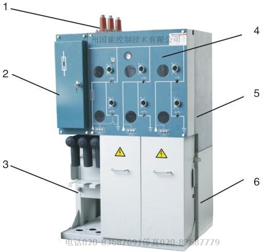
1双通套管(单元扩展用)
2熔断器室
3电缆室
4操作机构
5充气单元
6底架
The outline and base structure of cubicle
1 Connecting bushing(for extending)
2 Fuse chamber
3 Cable chamber
4 Operating mechanism
5 Unit gas filled
6 Support frame
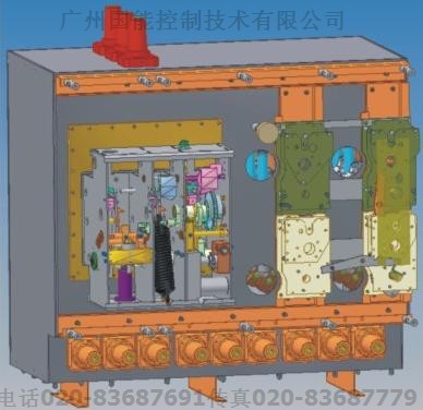
结构特点
产品由充气室,操作机构,箱体底架,电缆室,熔断器室及低压室等五部分组成:
1共箱式设计:多回路的一次元件安装在同一个充气室内,完成多项供配电功能,组合灵活.
2采用SF6气体作为绝缘介质,最大限度缩小了柜体的体积.
3采用屏蔽型电缆接头,绝缘表面接地可触摸,安全可靠,能适应恶劣的环境条件.
4采用压气式灭弧原理,SF6气体作为灭弧介质,额定转移电流达到2200A
5断路器采用真空灭弧,短路开断能力强,不会污染SF6气体
7充气室设有多个观察窗口,可从多个角度看到断口状态.
8开关柜设有带电显示器,气压表,压力释放装置等,操作安全可靠
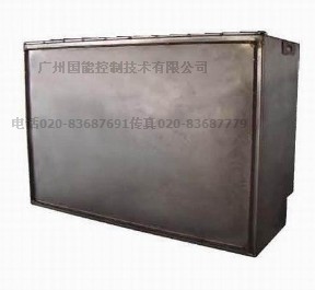
9充气室为不锈钢壳体,可靠接地,增加了电气安全性
10负荷开关安装在封闭的绝缘筒中,既减少了污染,又方便更换
11根据用户的需要,在柜体上方可以引出套管作为扩展单元用
12底架空间宽阔,可安装多分支电缆插头及避雷器等.
Features in configuration
The RMU consists of 5 portions :Gas filled chamber, Operation mechanism, Supporting frame,Cable chamber, Fuse chamber and Secondary circuit(LV) chamber
1 One tank design: Multi-circuit in one gas filled tank with agile combination to performance difference power distribution functions
2 With SF6 gas as insulated medium to reduce the volume greatly
3 Shield cable terminals with touchable surface and reliable safety character are suitable for abominable ambient condition
4 Using SF6 as the arc extinguishing medium ,the LBS which adopting gas-pressed are extinguishing principle is able to break the transfer current up to 2200A
5 The circuit breaker is vacuum type with high breaking capacity and no pollution to SF6 gas
6 There is a perfect mechanical interlock between LBS and ES.
7 The state of contacts can be chock in difference angles by eye easy from some viewing windows of tank filled
8 The cubicle is equipped with the living indicator, pressure gage and the over pressure releaser to ensure the safety of service
9 The tank filled with gas and made from stainless steel is earthing reliably to increase the electric safety
10 The fuse is barreled in insulated cylinder to prevent the pollution in which the fuse body is easy to replace
11 If need to extend to fit a bushing on the top of cubicle for extending is available
12 The multi-branch cable plugs and arresters can be fitted in bottom support chamber with vast space
Product code of manufacturer
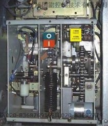
操动机构
手动或电动,弹簧储能快合快分操作.
Operating mechanism
Operating mechanism of LBS: Manual or motor,
Spring energy storing for performing fast C & fast O operation.
手动分合闸操作;合闸时快速合闸装置使主地刀具有关合短路
电流的能力.
Operating mechanism of ES:
Manual operating; The main earthing blade is provided with the capacity of making short circult current due its fast closing design.
There is a rellable mechanical interlock between the LBS and the ES,when the LBS is in close position the ES cannot be closed;when,contrarily,the ES is closed the LBS can not be closed.
手动或电动操作使合闸,分闸弹簧同时储能,操作机构储能后显示”弹簧已储能”..合闸时,合闸弹簧释能快速合闸,分闸弹簧维持储能状态;若有故障电流使熔断器熔断,则熔断器的撞针使脱扣器动作开关快速断开.分闸时,通过手动或电动方式反方向操作(或通过分励脱扣器,熔断器撞击装置动作)使分闸弹簧脱扣后迅速释放以实现”快分”.
The mechanism of LBS-Fuse combination unit:
Manual or motor energize the O & C springs synchronously, The indicator of “ Spring energized “will appear after spring energized.
When closing ,the C spring release the energy stored quickly to close the LBS, the O spring keeps in energized estate, if the fuse is melted due to the fault current, then the firing-pin of fuse strikes the releaser of LBS to open quickly.
When opening, the O spring will release the stored energy to perform the “ast open” by the opposition-operation of manual or motor (or by the shunt releaser or by the strike action of the firing-pin of fuse)
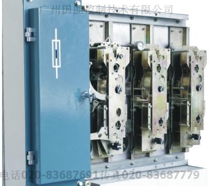
断路器操动机构
采用弹簧操作机构,通过波纹管密封装置传递分合闸动力.
Operating mechanism of CB
Spring mechanism drives the close or open energy to CB by seal bellows driver
充气室