Ring network cabinet switch controller Protector OEM/ODM
Tank open and close the guard dog boundary part switch controller is introduced
Dividing line switch controller box open and close the guard dog
Selection guidelines:
A new generation of intuitive dial type controller set valued
NKR - 6 for box type circuit breaker
NKR - 5 for box type load switch
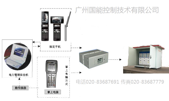
ABF - 2001 type: type LCD and close control with output, with PDA function;
 1. An overview of the
1.1 main purpose and scope of application
10 kv overhead power distribution line or cable line T meet user internal failure occurs, such as the fault in the line, or although fault happens in the user into the inside line switch and its protection action time and outlet switch substation protection with no at that time, all can cause line switch tripping protection of transformer substation. If the nature of the fault is permanent, substation overlap is not successful, then a medium voltage user limits accident will make the whole distribution circuit power outages, movements in the distribution of common accidents, will cause bad influence to society.
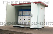
Tank-type watchdog SF6 insulated all closed boundary between open and close the profile
 Distribution network watchdog dividing line switch in 10 kV line application can greatly reduce the trouble-free of line of collateral forced outage, narrowing the scope of failure blackout, shorten the blackout time users, so as to improve the power supply reliability of the user.
Boundary load switch to load switch and microcomputer protection measurement and control, and communications module integrated device, with the power distribution network configuration, small volume, less investment, the application of it to improve the safety and reliability of the distribution network, is of great significance to ensure the safe operation of power grid.
User watchdog boundary load switch is an ideal equipment to solve the above affected accident, the equipment is installed on the 10 kv overhead power distribution line or cable lines, the responsibility of the boundary of can realize automatic removal of single-phase grounding fault and short-circuit fault isolation and automatically. Ensure that the fault users of electricity safety.
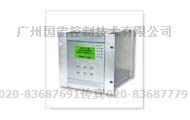
ABF user boundary load switch controller is specially used for separating the switch intelligent control of the ontology. Achieve protection control and communication functions, the controller and switch ontology through the control cable and air connectors for electrical connection, its protection and automatic monitoring function. The product is widely used in urban and rural power distribution line or cable 10 kv overhead line. Shape as shown in figure 1.
The controller figure shape
1.2 use environmental conditions
A) temperature: outdoor - 40 ℃ ~ + 70 ℃ the highest annual average temperature of 20 ℃, the highest average temperature 3 ℃
B) seismic capacity: the ground level 0.3 g and 0.15 g ground vertical acceleration and acceleration role in last three are
Wave, safety coefficient is 1.67
C) maximum daily temperature 25 ℃
D) the sunshine intensity: 0.1 W/cm2 (wind speed 0.5 m/s)
E) maximum wind speed: 25 m/s or less
F) the largest ice thickness: 10 mm
G) operating environment: outdoor, no inflammable, explosive danger, chemical corrosion and the site of violent vibration
H) neutral point grounding way: neutral point grounding, neutral point via arc suppression coil grounding, neutral point by the low resistance grounding.
2. The technical parameters
2.1 switch ontology needs to provide technical parameters (see table 1)
With the switch will need to provide parameters
table 1
|
|
单 位
|
数 据
|
|
1
|
额定电压
|
kV
|
|
|
2
|
额定电流
|
A
|
|
|
3
|
额定短路关合电流(峰值)
|
kA
|
|
|
4
|
额定电流开关性能
|
次
|
|
|
5
|
分闸时间
|
ms
|
|
|
6
|
合闸弹跳时间
|
ms
|
|
|
7
|
开关合(分)闸同期性
|
ms
|
|
|
8
|
内置线路电流互感器变比
|
|
600:1
|
|
9
|
分合闸电压
|
V
|
|
Serial number name unit data
Rated voltage 1 kV
Rated current 2 A,
3 rated short circuit close current kA (peak)
4 rated current switch performance
5 break-brake time ms
6 closing bounce time Ms
7 switch (points) brake synchronism ms
8 built-in line current transformer variable than 600:1
9 switching voltage V
2.2 controller parameters (see table 2)
Table 2.
|
序号
|
项目
|
规定值
|
备注
|
|
1
|
输入工作电压
|
AC220V
|
|
|
2
|
输入工作电压频率
|
50Hz
|
|
|
3
|
输入工作电压允许波动范围
|
±10%
|
|
|
4
|
整机功耗
|
<10W
|
|
|
5
|
输出电压(合闸/分闸操作)
|
220VAV/60VDC
|
|
|
6
|
输出控制接点容量
|
60A
|
|
|
8
|
采样相电流输入值
|
0~10A
|
10A以上允许饱和
|
|
9
|
采样零序电流输入值
|
0~50A
|
10A以上允许饱和,50A正常跳闸
|
|
10
|
电量输入值允许采样误差
|
±4%
|
饱和区不作要求
|
|
11
|
分闸闭锁一次电流整定范围
|
120-600A
|
|
|
12
|
相间故障确认时间值
|
0.3S
|
|
|
13
|
零序保护一次电流整定范围
|
0.2~4.0A
|
步长0.2A(0=退出)
|
|
14
|
零序保护动作延时时间值
|
0.2~2.0 S
|
步长0.2S
|
|
15
|
低电压动作值
|
10~160V
|
|
|
16
|
简单遥控器距离
|
不小于30米
|
|
|
17
|
抗高频干扰
|
IV级
|
GB/T15153.1
|
|
18
|
静电放电
|
V级
|
GB/T15153.1
|
|
19
|
浪涌干扰
|
IV级
|
GB/T15153.1
|
|
20
|
快速瞬变
|
4000V
|
参考GB/T15153.1
|
E. note number project
1 enter working voltage is AC220V
2 input voltage frequency 50 hz
3 input voltage allowed range + / - 10%
4 the machine power consumption < 10 w
5 output voltage (closing/break-brake operations) 220 vav / 60 VDC
6 output control contact capacity 60 a
8 sampling phase current input value of 0 ~ 10 a more than 10 a saturation are allowed
9 sampling zero sequence current input values 0 ~ 50 a more than 10 a allow saturated, 50 a normal trip
10 power input values to allow sampling error of plus or minus 4% saturated zone does not make the request
11 points brake atresia a current setting range 120-600 - a
12 and fault set the time value of 0.3 S
13 A zero sequence pilot protection current setting range of 0.2 ~ 0.2 A step 0.2 A (0 = exit)
14 zero sequence protection action delay time value 0.2 ~ 2.0 S step 0.2 S
15 action value 10 ~ 160 v low voltage
16 simple remote control distance not less than 30 meters
Level IV GB/T15153.1 17 resistance to high frequency interference
18 GB/T15153.1 electrostatic discharge V level
Level IV GB/T15153.1
19 surge interference
20 GB/T15153.1 transient 4000 v reference
3. The function and characteristics
3.1 the function of the controller
* LED status indicator
* current brake atresia
* and fault identification
* the event log
* zero sequence protection
* real time clock
* PDA measurement and control (except ABF - 2003)
* remote control (note: the PDA brake control points, the remote control switch; invalid ABF - 2003 type main remote control points after the brake, auxiliary remote control switch is invalid)
The characteristics of the 3.2 controller
* points maloperation prevention design of software and hardware, and switching circuit and the jump function;
* zero sequence current can distinguish between area and zone fault;
* remote control points and closing adopted to prevent maloperation design;
* parameters can be set by encoding digital switch or PDA Settings;
* parameters can be made of PDA reading (except ABF - 2003).
3.3 structure characteristics
A) controller for independent sealing body, cylindrical structure, type of microcomputer relay protection and monitoring device;
B) controller has strong weatherability, anti condensation protection characteristics and the structure characteristics of small size light weight;
C) by air connectors and multi-core control cables and switch ontology to connect, connect good reliability, high protection grade.
4. Line fault processing
Controller input signal, A total of four, A phase current, C phase current and zero sequence current and voltage PT. Controller through the real-time monitoring value of the analog quantities and compared with the fixed value to determine the line fault, and thus for the corresponding processing. In the table below for the different system of fault handling results:
| |
|
fault protection treatment
故障点保护处理
|
|
The single-phase grounding fault
|
Non-ground neutral system user limits
中性点不接地系统用户界内
|
single-phase earth fault judgement for permanent ground immediately after trip
判定为永久接地后立即跳闸
|
Neutral point via arc suppression coil grounding user limits
中性点经消弧线圈接地用户界内
|
Neutral point via small resistance grounding user limits
中性点经小电阻接地用户界内
|
Before the substation tripping protection action
先于变电站保护动作跳闸
|
Non-ground system users out
中性点不接地系统用户界外
|
|
Neutral point via arc suppression coil grounded out by the user
中性点经消弧线圈接地用户界外
|
Neutral point via small resistance grounding out by the user
中性点经小电阻接地用户界外
|
|
Interphase short circuit fault
|
User limits brake fault
用户界内故障
|
电源侧断路器跳闸停电后,
分界负荷开关分闸Power supply side of the substation breaker tripping outage, separating brake load switch points
|
The user out fault
用户界外故障
|
|
Status indicates:
TV lamp: electricity, light - controller out the controller without electricity
Running lights, light - program is running normal clearance, normally on abnormal or often destroyed - program
Abnormal light: light - self-checking abnormalities, destroy the normal - testing
Grounding: bright lights - zero sequence values of overdetermined, out - zero sequence is not constant value
Ultra short street lamp: bright - alternate with constant value, out - and not fixed value;
Blocking the light, bright, point out atresia, out - point out without blocking.
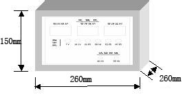
5. Installation and connection
5.1 installation diagram
Dimension: 260 * 260 * 260 units: mm
Figure 2: switch to the controller installation schematic diagram
5.2 controller connected to the switch
Device working power can use ac voltage 220 v power supply or charging current transformer, switch trip, directly by the back-up power to power a device.
Switch to provide device switch ontology position state, such as energy storage state breaker, isolating the position signal. In general, these signals in the form of auxiliary air contact provided. Jump feed motion control switch rated current 1 a / 5 a, action pulse width is commonly 50 ~ 200 ms. Permanent magnetic actuator can also be allocated to the switch.
Device to provide external 20 core power cable, all equipped with serial number, the wiring diagram is as follows:
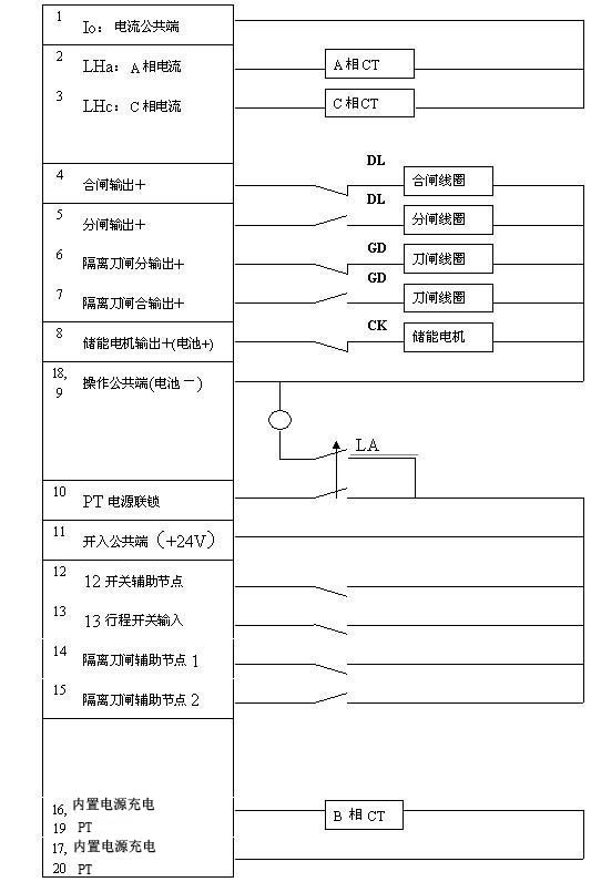
Diagram: a device connected to the switch body figure
Note: output control circuit cannot be directly connected to switch coil, you should set the secondary node of the switch series circuit, detailed methods refer to instruction manual of the switch.
5.3 installation diagram
The device is designed to be installed directly on the switch body, on the back of the chassis, with four pillars M10 * 30 screw, the corresponding directly mounted at the side of the switch of the ontology.
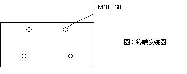
Can be changed according to user needs, installation.
5.4 communication port (optional)
Terminal through the optical transceiver and distribution master station to exchange information. This port is a RS232 optical transceiver, baud rate from 2400 to 38400 BPS. Communications equipment (DCE) can be: GPRS/CDMA / 3 g TDCDMA terminal, fiber modem, cable modem, distribution carrier communication machine, wireless data transmission radio, etc. For the use of communication equipment, please see the user manual of the device.
6. The control panel
6.1 control panel schematic diagram
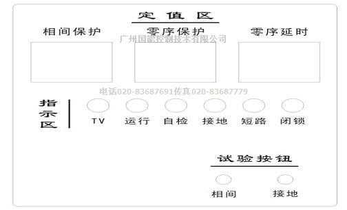
Figure 8: panel
6.2 the use of the key introduction
Press "grounding" test to simulate ground fault; According to the simulated interphase fault "and" test button.
6.3 parameter Settings window on the back cover
7. The size and weight
(unit: mm weighing less than: 3... 5 kg)
Figure 9: structure shape