from CT power supply ring network cabinet ABYNSR - 200 microcomputer relay protection OEM/ODM measurement and control device

An overview,
ABYNSR - 200 is derived from the power supply ring network cabinet of microcomputer protection measurement and control device is mainly used for 35 kv / 12 kv high-voltage feeder of intelligent control, are widely used in power distribution network automation system
Intelligent box change/intelligent outdoor switch/intelligent ring network cabinet/intelligent outdoor branch/intelligent outdoor measurement control electric device.
It combines the latest digital control technology, strong resistance to interference and fault self-diagnosis software repair technology to a body, with minimal maintenance workload for high voltage power system relay protection, fault location, monitoring, detection of power quality and provides advanced management skills such as communication. Due to its internal adopted the high reliability of electronic components and advanced protection, self-checking, since maintenance technique, so the microcomputer protection measurement and control device in addition to outside every three to five years to replace the battery almost do not need any maintenance and maintenance.
Second, the technical performance and indicators
1 the basic function
- microcomputer protection function: a quick break, limit per hour break, over current protection, zero sequence protection, loss of pressure protection function, flexible setting definite time how fast speed characteristic, users can be set up and delay protection setting, cooling load startup time delay function. Manual and automatic mode setting data modification. Inverse time, fixed time limit over-current protection (0.1-64 seconds continuous adjustable, can use the ANSI/IEC standard 17 solidification curve, can also be loaded user to compile a custom curve.
- reclosing function: can set up three reclosing four points (ka), the freedom to choose number of coincidence and overlap intervals. Setting action can use internal curing 14 set of fast and slow combination, also can be custom action sequence by the user.
- network reconfiguration function: ring net runtime, according to the feature set in advance, realize distributed intelligence. Under fault condition automatic isolation fault zone, automatic transfer of power supply, to restore the fault area power supply.
All kinds of operation data record and the event log. Record up to 1000 times.
- which can realize remote control, remote sensing, remote communication function. Such as operation, the control of various states of the distance monitoring, various measured values and the event log of the distance display, all kinds of fixed value of the distance adjustment. (network)
- communication interface and protocol: equipped with RS485 / RS232 standard communication, support optical fiber, cable, and other communication methods, support universal remote statute, ACTS as a remote terminal in the distribution automation system.
- system work is given priority to with grid current or voltage of power supply, battery backup. By adopting the technology of power pump, even if the battery voltage drops to 50% when closing switch can also be reliable points. Battery system adopts advanced charging circuit current control technology and numerical control automatic completely discharge activation treatment technology on a regular basis, extend battery life.
- work in parallel and hardware control system implemented by monitoring technology, to ensure system reliable operation.
- resistant lightning surges, circuit resistance, resistance to strong electromagnetic pulse interference device and technology. Control unit of the electromagnetic interference resistance meet the following requirements: ability to resist disturbance, fast transient oscillation wave/pulse group of immunity ability, impact immunity ability put reactance, electrostatic interference ability to the provisions of GB/T17626-1998 the third harshness.
- can upgrade the software and data update in system.
2. The microcomputer protection measurement and control device
(1), analog input: 6 road ac input. Collecting electricity flow 3 road, 3 road voltage should be increased according to user requirements () the rated ac current input: 1 a / 5 a; Rated input voltage: 100 v
Continuous rated ac signal input overload capacity: 400%, 3200% for 4 s
(2), A/D conversion resolution: 12. Sampling method: ac sampling, wave a week 64 points, sampling accuracy better than 1%
(3), the switch quantity input, output, 4 way switch input (can increase to 12 road). Can be a switch position signal, power supply alarm, remote control of switching signals, etc.; Two-way relay contact output for points, switching power supply control, etc. Contact capacity: 12.5 A, 48 VDC or 16. A, 220 vac (empty contact); Switching impulse voltage range is 38 v - 72 - v, rated current 10-20. A, a pulse duration of 40-60 ms; (can be adjusted depending on the type of switch)
(4), the panel or the distance setting: the setting value, the sequence of operation, overlapping intervals, a second characteristic curve and reset time parameters can be set on the panel or the remote. Inverse time, fixed time limit over-current protection (0.1-256 seconds continuous adjustable, can be used in accordance with ANSI/IEC standard internal curing curve, can also be loaded user to compile a custom curve.
Sequence of operation (adjustable) : O - t1 - CO - t2 - CO - t3 - CO - t3 - CO - atresia (see table 1)
(5), communication function, can according to the requirements of the user). Through RS - 485/232 communication port turn optical fiber or carrier which can realize remote operation, remote communication, remote control, and the distance parameter setting. Communication agreement IEC870-5-101 standard.
(6), the working conditions: outdoor installation on the pillars. Temperature: - 25 ℃ and 40 ℃) ∽ 85 ℃, relative humidity: 95% 0 ∽.
(7), which can record 1000 times line quality information and feed motion state information (time, over current value and phase sequence, and setting value, battery voltage, etc.). Allowed in continuous loss of electric grid system reliable data recovery within 30 days.
(8), the control unit of the electromagnetic interference resistance meet the following requirements: ability to resist disturbance, fast transient oscillation wave/pulse group of immunity ability, impact immunity ability put reactance, electrostatic interference ability according to provisions of GB/T17626-1998 third grade requirements.
Three, the basic principle of microcomputer protection measurement and control device
3.1 the microcomputer protection basic working principle of the measurement and control device
When the load side of the microcomputer protection measurement and control device failure occurs, the fault current signal comes after switch the current transformer in the body perception into current monitoring circuit of the electronic control unit, control unit for processing and recognition of this current signal, when the judge current signal is greater than the setting in advance the minimum starting current, microcomputer module automatically start, according to a predetermined action program, by executing circuit automatically to the operating mechanism of the points, closing coil signal action, operation mechanism and drive the output shaft and the rotating mechanism, causing the body to switch the primary loop dynamic contact to complete the corresponding open and close action. In the process of operation order, if the fault has been eliminate (i.e., instantaneous fault), the control unit will no longer send break-brake signals, until a predetermined reduction and automatic reset when time comes, restore to the original state; If the fault persists (i.e., permanent fault), the control unit will be completely according to beforehand setting operation sequence number after closure. Until the command switch, the control unit to remove atresia and restore to its original state.
3.2, power supply system
Normal operation of power grid, the battery is in floating charge state, the machine parts supply also entirely by machine configuration of CT/PT power supply, even take off the battery, at this time also does not affect the machine back to work. Only when the grid system is a permanent fault, CT power supply gap to turn power supply by battery system. To a fault appears permanent fault repair time interval is not more than three days, the reclosing controller can be put into normal operation at any time. After the operation, CT/PT is automatically added to the battery system electric power supply system or enter a floating state. Due to the power grid in the fault state time less commonly, so the battery inside the machine basically idle, thus greatly extend the battery life, eliminates the trouble to conventional controller often need to change the battery.
Battery output points can be for two road, all the way through the switch of the control unit output circuit to direct drive operating mechanism of closing coil (or) ac drives. Another way to send control circuit of power supply module, the power converter for the use of control circuit. The machine chooses maintenance-free battery temperature range is 00 c ~ 700 c, the service life not less than five years.
Four instructions
4.1 keyboard:
(1) "keyboard on/off" button: open/exit the state of the keyboard (only open) rear can display and other operation of the keyboard.
(2) the "" button: the left option to show/setting project; In the condition of setting choose digital bits to the left;
(3) "" button: to the right to choose show/setting project; In the condition of setting to the right to choose Numbers;
(4) "bring / +" key: in the condition of setting, increased key value;
(5) "▼ / -" key: in the condition of set, the set value reduce key;
(6) "self-check" button: check Settings (series of products in use, this set of equipment not use);
(7) "cancel" button: in the condition of setting to cancel the current Settings and exit (current return original state);
(8) "ok" button: the state of the current project Settings; In the condition of setting determine Settings and exit;
4.2 display and operating instructions:
To view:
A. press the "on/off keyboard" (under the premise that connect the PT for socket CH3, see 3.1), the machine enter into the state of the keyboard, LCD screen open at the same time.
B. Press the "/" button, select need to view project (i.e., flashing project), data display shows the current data of the project.
C. again, press the "on/off keyboard", state of the machine out of the keyboard, LCD display and shut down.
Setting:
D. Press the "on/off keyboard", the machine enter into the state of the keyboard,
E. press "select" button, make the whole project to the setting or measuring project (both flashing project)
F. Press "ok" button, according to the need of setting value according to add or press the "+" "-" to reduce the value
G. then press "ok" button, exit the program setting; Click "cancel" button to cancel the setting value;
H. if you need other project setting, repeat B, C, D;
I. after setting, press the "on/off keyboard", the machine will be written to the new setting value, and exit the keyboard status; The machine will work under the new setting parameters;
J. break-brake minimum starting current setting method: setting the minimum starting current according to the following formula:
The set values for the minimum starting current = % X current transformer variable ratio
For example: transformer than 400:1 setting value 25%,
The minimum starting current is: 25% X400 = 100
K. first, two, three, four times the reclosing time interval set: coincidence time interval is refers to the previous points interval between instructions to perform the instructions. The first reclosing time interval 0.3 180 seconds continuous adjustable. Other reclosing time adjustable 2-1000 seconds
L. - second characteristic curve of the delay break-brake characteristic curve, is actually "hotline", both curve equal amount of each point of the heat capacity. When there is more than setting on a line of break-brake minimum starting current, the reclosing make action, according to the process of setting the points close break-brake delay decreases with the increase of the fault current. Fast time delay curve (i.e. INST curve) of a fixed, don't need to adjust. Slow delay curve, a total of 16, the coefficient of 0.1-1.6 delay curve respectively.
M. order: (see table 1), A fast points, B is after slow action corresponding points and requirements. For example: 2 a2b, two fast and slow;
N. reset time: reset time is pointed out that current and fault current (more than setting in advance of break-brake minimum starting current) controller microcomputer action to fault current microcomputer reset time interval. 0.3 180 seconds continuous adjustable reset time, the choice of the reset time should be greater than the selected - second delay curve of the largest delay time
O. the machine number: the number is to facilitate the management of distribution network automation, the same interval of each machine controller specified only number. From 000 to 1000. Record the serial number refers to the line fault occurs after the current controller on a switching command sequence according to the number of good. Just put into operation for the controller, record the serial number default is 001. Adjustment method of parameters for reference to other methods.
P. native date, time, in order to facilitate fault current in line after analysis and processing, the machine in the event of a failure of current parameters and time records, along with all this requires that this machine has an accurate clock system, so the system put into operation is required to clock system calibration. To record the machine number, serial number, this machine is the adjustment of the date, time, accurate or not will not affect the other control parameters of the controller.
Self-checking:
A. press the "on/off keyboard", the machine enter into the state of the keyboard,
B. according to the "self-check" button, the machine into the self-check state, relay inside machine set, set up regular action, the indicator lights on the panel regular flashing at the same time;
C. after the self-inspection, press the "on/off keyboard", the machine out of state of the keyboard.
4.3 the connector signal:
CH1: plug control output (4) : 1, blue (switching output) 2, white (break-brake output)
3, orange/red (closing) 4, yellow/green brake (points)
CH2 plug: signal input (5) 1, color (manual switch) 2, white (manual brake)
3, color (break-brake instructions) 4, yellow (closing instructions) 5, black (ground)
CH3 plug: mutual inductance input (6) : (PTA) + 2 1, orange, red (PTA)
3, yellow + (PTB) 4, green (PTB)
5, blue (empty) 6, white (empty)
4.4 before installation should be the following work:
(1), a visual inspection. When unpacking the case check placement of the whole machine is correct.
(2), the door is open the reclosing control, check if there's any loose for the controller and exceptions. If normal, can proceed the following checks and setting process.
(3), the plug and socket is loose
(4), in the introspection: this machine should be checked before put into operation. Method is: connected to PT socket (CH3), open the host power switch, according to the requirements of the parameters setting and adjustment, open again after closed disk, see the setting data is correct, if correct can be put into operation.
The installation of five microcomputer protection measurement and control device
5.1
ABYNSR - 200 is derived from the power supply ring network cabinet of microcomputer protection measurement and control device is composed of motherboard, panels, the total weight of 3 kg.
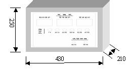
1 has the LCD for installation dimension length X width X height = 430 x250x210mm, circuit connection is convenient, easy maintenance and repair.
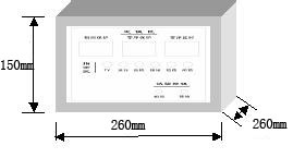
Appearance size 2 without LCD: 260 x 260 x 150 units: mm
5.2 controller connected to the switch
Device working power can use ac voltage 220 v power supply or charging current transformer, switch trip, directly by the back-up power to power a device.
Switch to provide device switch ontology position state, such as energy storage state breaker, isolating the position signal. In general, these signals in the form of auxiliary air contact provided. Jump feed motion control switch rated current 1 a / 5 a, action pulse width is commonly 50 ~ 200 ms. Permanent magnetic actuator can also be allocated to the switch.
Device to provide external 20 core power cable, all equipped with serial number, the wiring diagram is as follows:
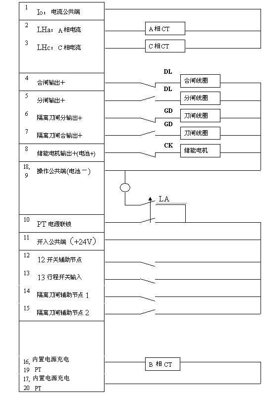
Diagram: a device connected to the switch body figure
Note: output control circuit cannot be directly connected to switch coil, you should set the secondary node of the switch series circuit, detailed methods refer to instruction manual of the switch.
5.3 installation diagram
The device is designed to be installed directly on the switch body, on the back of the chassis, with four pillars M10 * 30 screw, the corresponding directly mounted at the side of the switch of the ontology.
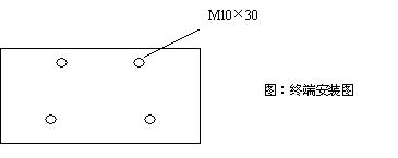
Can be changed according to user needs, installation.
5.4 communication port (optional)
Terminal through the optical transceiver and distribution master station to exchange information. This port is a RS232 optical transceiver, baud rate from 2400 to 38400 BPS. Communications equipment (DCE) can be: GPRS/CDMA / 3 g TDCDMA terminal, fiber modem, cable modem, distribution carrier communication machine, wireless data transmission radio, etc. For the use of communication equipment, please see the user manual of the device.
6. The control panel
6.1 control panel schematic diagram
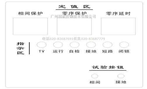
Figure 8: panel
6.2 the use of the key introduction
Press "grounding" test to simulate ground fault; According to the simulated interphase fault "and" test button.
6.3 parameter Settings window on the back cover
7. The size and weight
(unit: mm weighing less than: 3... 5 kg)
Figure 9: structure shape