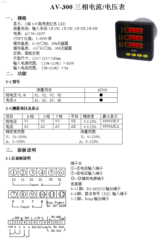
三相电流/电压表AV-300
1, communication
The 1-1 protocol
The communication agreement of Modus protocol - RTU model.
Code
8 bits of the 2 bit system numerical
The start bit
1
Pattern
Asynchronous
Data length
8
Parity
No
Stop bit
2
Error checking
CRC (cyclic redundancy code)
Initial signs of greater than 4 bytes = time
Address code = 1 bytes
Function code = 1 bytes
The data area of =N bytes
Error check = 16 CRC code
Marks the end of more than 4 bytes = time
The structure of 1-2
Address code
Function code
The data area
Check code
8 bit
8 bit
N x 8 bit
16 bit
1-3 address area
Address code as the starting byte message group (8 bits), the address will be set by the user is received by the master to send the message from the station from the byte representation of 1~247. Each slave station must have a unique position code, and only in line with the address codes from the station to respond. When the slave response message, the address code indicates where the message from.
1-4 function area
The master sends the function code to perform the tasks from the station to tell, the following is a list of function code has a meaning and the specific operation.
Code
Meaning
Operation
03
Read data
Read the current register one or more of the binary value
06
Preset single register
The set of binary value written to a single register
The 1-5 data area
The data area includes the need from the station to perform the act or from the station acquisition anti send messages, these messages can be numerical, reference address etc.. For example: the function code tells the read register values from the station, then the data region must contain the starting address register to read and read length, for different from the station, address and data messages are not the same.
1-6 error checking code
Master or discriminate whether the error from the station to receive messages available check code, when the message in the transmission process, due to the electronic news or other interference, and produce uncertainty, error checking code can ensure the master or slave error during the transmission of a message is not maintained, so the establishment of system reliability. (CRC-16 calibration method for error checking mining)
Address code, function code, the data area and an error message is composed of the format is the same *
1-7 error checking code
Cyclic redundancy code (CRC) contains 2 bytes, 16 bits of the binary CRC code transmitted by the numerical computing devices arranged on the tail, send a message. Receiving message device receives information re calculation of CRC code, compares the calculated CRC code is consistent with the received, if they do not conform to, is that error, namely the communications data is not identified on the implementation of error handling.
Calculation of CRC code:
Preset 16 bit registers sixteen carry FFFF (i.e., all 1). Call this the CRC register.
The first 8 bit digital tuples do exclusive or operation with the 16 bit CRC register is the low byte, to put the results in the CRC register in.
The CRS register contents right a bit (toward the low yuan), fill the highest bit 0, and then check the lsb.
If the least significant bit is 0: repeat third steps (once again shift).
If the least significant bit 1:CRC register and A001 polynomials (1010000000000001) do the exclusive or operation.
Repeat steps 3 and 4, know right 8 times so far, all 8 digit bytes all processing.
Repeat steps 2 through 5, for the next 8 digits bytes all processing.
Finally got the CRC register is CRC code.
2, communication function description
The 2-1 reads the register contents: (Function code:03H)
This function allows the user to select measurements, recording data and system parameter setting
Address
Function
Data start
Addr
Data of
Regs
CRC 16
Low
CRC 16
Hi
01H
03H
03H
00H
Response: the return data contains a function from the station location, code, data length data bytes and check code.
Address
Function
Data count
Data
CRC 16
Low
CRC 16
Hi
01H
03H
02H
27H
0
2-2 change a single register contents: (Function code:06H)
This function allows the user to change any single register location of license, but the change data must be in the range of the received, when this table in the normal work state, this function can be performed at any time.
Address
Function
Data of
Regs
Value
CRC 16
Low
CRC 16
Hi
01H
06H
0BH
00H
Response: in a normal response, response is usually delayed to register after changes
Address
Function
Data of
Regs
Value
CRC 16
Low
CRC 16
Hi
01H
06H
0BH
00H
2-3 error message
Address
Function
Error code
CRC 16
Low
CRC 16
Hi
01H
6EH
02H
0
Change the highest bit function code for high
Error code: 01 = error function code (Error Function)
02= error data location (Error Data Address)
03 = false data value (Error Data Value)
3, data structure:
Any parameters of 1 value of the instrument is composed of an integer and a decimal point (integer value to remove the decimal point value of meter display value).
The 2 parameter values over a range of 255 to two bytes, or 1 bytes.
For example: voltage display for 355.5V
Then the voltage value of 3555 (sixteen m 0X0DE3)
High voltage is 0X0D bytes
Low voltage is 0XZ3 bytes
The decimal point voltage is 1
Address table
0
The high byte of A phase voltage
Unsigned char
0~255
1
Low byte A phase voltage
Unsigned char
0~255
2
The high byte of B phase voltage
Unsigned char
0~255
3
Low byte B phase voltage
Unsigned char
0~255
4
Low byte C phase voltage
Unsigned char
0~255
5
Low byte C phase voltage
Unsigned char
0~255
6
High byte A phase current
Unsigned char
0~255
7
Low byte A phase current
Unsigned char
0~255
8
High byte B phase current
Unsigned char
0~255
9
High byte B phase current
Unsigned char
0~255
10
High byte C phase current
Unsigned char
0~255
11
High byte C phase current
Unsigned char
0~255
12
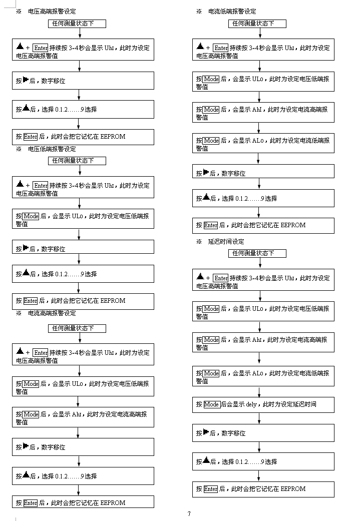
Voltage high end alarm high byte values
Unsigned char
0~255
13
Low voltage high end alarm byte values
Unsigned char
0~255
14
Lower voltage alarm high byte values
Unsigned char
0~255
15
Lower voltage alarm low byte values
Unsigned char
0~255
16
The current high-end alarm high byte values
Unsigned char
0~255
17
The current high-end alarm low byte values
Unsigned char
0~255
18
The current low-end alarm high byte values
Unsigned char
0~255
19
The current low-end alarm low byte values
Unsigned char
0~255
20
Alarm high byte delay time
Unsigned char
0~255
21
Alarm low byte delay time
Unsigned char
0~255
22
From the machine.
Unsigned char
0~255
23
The baud rate
Unsigned char
0~255
Note: the baud rate 0---->4800
The baud rate is 1---->9600
The baud rate is 2---->19200
1、通讯
1-1通讯协定
采用Modus protocol –RTU模式之通讯协定。
|
编码
|
8位元之2进位制数值
|
|
起始位
|
1位
|
|
模式
|
异步
|
|
数据长度
|
8位
|
|
奇偶校验
|
无
|
|
停止位
|
2位
|
|
错误校验
|
CRC(冗余循环码)
|
起始标志=≥4字节的时间
位址码 = 1字节
功能码 = 1字节
数据区 =N字节
错误校验 = 16位CRC码
结束标志=≥4字节的时间
1-2结构
|
位址码
|
功能码
|
数据区
|
校验码
|
|
8位元
|
8位元
|
N×8位元
|
16位元
|
1-3位址区
位址码为讯息组的起始位元组(8位元),从1~247这个位元组表示由用户设置位址的从站将接收由主站发送来的讯息。每个从站都必须有唯一的位置码,并且只有符合位址码之从站才能回应。当从站回应讯息时,其位址码表示其讯息来自何处。
1-4功能区
主站发送之功能码告诉从站要执行之任务,以下列出功能码都有具体的含义及操作。
|
代码
|
含义
|
操作
|
|
03
|
读取数据
|
读取当前暂存器一个或多个之二进位值
|
|
06
|
预置单一暂存器
|
把设置之二进位值写入单一暂存器
|
1-5数据区
数据区包含需要从站执行之动作或由从站采集的反送讯息,这些讯息可以是数值,参考地址等等。例如:功能码告诉从站读取暂存器的值,则数据区必包含要读取暂存器的起始位址及读取长度,对于不同的从站,位址和数据讯息都不相同。
1-6错误校验码
主站或从站可用校验码进行判别接收讯息是否出错,当讯息在传送过程中,由于电子讯或其他的干扰,而产生不确定性的变化,错误校验码可以保证主站或从站在传送过程中出错的讯息不被认定,如此可确立系统的可靠性。(错误校验采CRC-16校验方法)
- 位址码,功能码,数据区和错误讯息组成的格式都是相同的※
1-7错误校验码
冗余循环码(CRC)包含2个位元组,16位元二进位数值CRC码由发送设备计算,置于发送讯息的尾部。接收讯息设备再重新计算接收到讯息CRC码,比较计算得到的CRC码是否与接收到的相符合,如果两者不相符合,则表明出错,即传讯资料不被确定就执行错误处理。
计算CRC码的步骤:
- 预置16位元暂存器为十六进位FFFF(即全为1)。称此为CRC之暂存器。
- 把第一个8位数位元组与16位CRC暂存器之较低位元组做互斥或运算,把结果置于CRC暂存器内。
- 把CRS暂存器的内容右移一位元(朝低元),用0填补最高位元,再验查最低位元。
- 如果最低位元为0:重复第3步骤(再次移位)。
如果最低位元为1:CRC暂存器与多项式A001(1010 0000 0000 0001)做互斥或运算。
- 重复步骤3和4,知道右移8次为止,将全部8位数位元组全部进行处理。
- 重复步骤2到步骤5,进行下一个8位数位元组全部进行处理。
- 最后得到的CRC暂存器即为CRC码。
2、通讯功能说明
2-1读取暂存器内容:(Function code:03H)
此一功能允许使用者选取测量值,记录资料及系统所设定参数
|
Address
|
Function
|
Data start
Addr
|
Data of
Regs
|
CRC 16
Low
|
CRC 16
Hi
|
|
01H
|
03H
|
03H
|
00H
|
|
|
Response:所回传的资料中包含了从站的位置,功能码,资料的长度,资料位元组及检查码。
|
Address
|
Function
|
Data count
|
Data
|
CRC 16
Low
|
CRC 16
Hi
|
|
01H
|
03H
|
02H
|
27H
|
0
|
|
2-2变更单一暂存器的内容:(Function code:06H)
此一功能允许使用者变更任何经许可的单一暂存器位置,但其变更的资料必须是在被接收的范围内,当此表在正常的工作状态下,此功能在任何时间均可执行。
|
Address
|
Function
|
Data of
Regs
|
Value
|
CRC 16
Low
|
CRC 16
Hi
|
|
01H
|
06H
|
0BH
|
00H
|
|
|
Response:在常态回应时,回应通常延迟至暂存器变更之后
|
Address
|
Function
|
Data of
Regs
|
Value
|
CRC 16
Low
|
CRC 16
Hi
|
|
01H
|
06H
|
0BH
|
00H
|
|
|
2-3错误讯息
|
Address
|
Function
|
Error code
|
CRC 16
Low
|
CRC 16
Hi
|
|
01H
|
6EH
|
02H
|
0
|
|
其功能码的最高位元更改为high
错误码:01 = 错误的功能码(Error Function)
02= 错误的资料位置(Error Data Address)
03 = 错误的资料值(Error Data Value)
3、数据结构:
1.仪表的任何一个参数值都是由一个整数值和一个小数点组成(整数值为仪表显示值去掉小数点的值)。
2.参数值范围超过255的为两个字节,否则为1个字节。
例如:电压显示为355.5V
那么电压值为3555(十六进制为0X0DE3)
即电压的高字节为0X0D
电压的低字节为0XZ3
电压的小数点位置为1
地址表
|
0
|
A相电压的高字节
|
unsigned char
|
0~255
|
|
1
|
A相电压的低字节
|
unsigned char
|
0~255
|
|
2
|
B相电压的高字节
|
unsigned char
|
0~255
|
|
3
|
B相电压的低字节
|
unsigned char
|
0~255
|
|
4
|
C相电压的低字节
|
unsigned char
|
0~255
|
|
5
|
C相电压的低字节
|
unsigned char
|
0~255
|
|
6
|
A相电流的高字节
|
unsigned char
|
0~255
|
|
7
|
A相电流的低字节
|
unsigned char
|
0~255
|
|
8
|
B相电流的高字节
|
unsigned char
|
0~255
|
|
9
|
B相电流的高字节
|
unsigned char
|
0~255
|
|
10
|
C相电流的高字节
|
unsigned char
|
0~255
|
|
11
|
C相电流的高字节
|
unsigned char
|
0~255
|
|
12
|
电压高端报警值的高字节
|
unsigned char
|
0~255
|
|
13
|
电压高端报警值的低字节
|
unsigned char
|
0~255
|
|
14
|
电压低端报警值的高字节
|
unsigned char
|
0~255
|
|
15
|
电压低端报警值的低字节
|
unsigned char
|
0~255
|
|
16
|
电流高端报警值的高字节
|
unsigned char
|
0~255
|
|
17
|
电流高端报警值的低字节
|
unsigned char
|
0~255
|
|
18
|
电流低端报警值的高字节
|
unsigned char
|
0~255
|
|
19
|
电流低端报警值的低字节
|
unsigned char
|
0~255
|
|
20
|
报警延迟时间的高字节
|
unsigned char
|
0~255
|
|
21
|
报警延迟时间的低字节
|
unsigned char
|
0~255
|
|
22
|
从机地址
|
unsigned char
|
0~255
|
|
23
|
波特率
|
unsigned char
|
0~255
|
备注:波特率0---->4800
波特率1---->9600
波特率2---->19200