|
|
 |
|
 |
|
 |
CONTACT |
 |
- ADDRESS:No.111 NanJing Road Shibi Industrial Area Panyu District of GuangZhou GuangDong,P.R.China
- TEL:+86 20 83687691
- FAX:+86 20 83687779
- Email:nkautomatic@126.com
|
|
|
 |
|
 |
|
|
|
|
|
|
| |
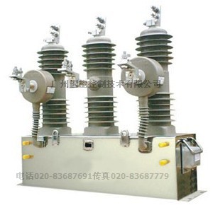
| NKZW32 permanent magnetic vacuum circuit breaker |
(three-phase one permanent magnet operating mechanism)
Since its establishment, the company has been engaged in the research and development of power automation systems based on the Guangdong Electric Power Grid Corporation Electric Power Research Institute and the State Grid Nanjing Automation Research Institute.
Our company's permanent magnet circuit breakers have many mechanical parts and eliminate the complicated mechanical lock and tripping system, so they have irreplaceable advantages: less failure, reliability, long life (more than 30,000 times), no lubrication At present, it has extensive power supply, coal mines, steel making, railways, etc.
The YCK380 series permanent magnet switch controller independently developed by our company, together with our permanent magnet operating mechanism, can realize the opening and closing operation of the circuit breaker, the over-current breaking protection, the watchdog protection, the wireless remote control operation, and the coincidence. The gate operation, as well as the distribution network automation function, make the switch a maintenance-free intelligent circuit breaker.
"People-oriented, quality win" is the company's business philosophy, "leading technology, customer service" for business purposes, "highly value product quality, professional and enterprising, tenacious, teamwork" as the spirit of enterprise. The company will always be market-oriented, focus on customer needs, strive to forge ahead, strive to develop and produce more and better high-tech products, and serve the customers.
1. Product Overview
1.1 main use
NKZW32-12/Y outdoor high voltage permanent magnet vacuum circuit breaker (hereinafter referred to as circuit breaker) is an outdoor power distribution equipment with a maximum rated voltage of 12kV and 50Hz three-phase AC. It is mainly used for breaking and closing the load current, overload current and short-circuit current in the power system. It is suitable for protection and control in power distribution systems of substations and industrial and mining enterprises. It is more suitable for rural power grids and frequently operated places, especially for the needs of urban network and rural network transformation.
This installation and installation manual specifies the main technical parameters of the circuit breaker, the product structure, and the principles and methods of operation, installation, use and maintenance.
1.2 reference standard
GB1984-2003 "AC high voltage circuit breaker"
GB/T11022-1999 "Common technical requirements for high-voltage switchgear and control equipment standards"
GB311.1-1997 "Insulation coordination of high voltage power transmission and transformation equipment: high voltage test technology"
GB3309-1989 "Mechanical test of high voltage switchgear at room temperature"
DL/T403-2000 "Technical Conditions for Ordering 12~40.5kV High Voltage Vacuum Circuit Breaker"
1.3 Environmental conditions used
1.3.1 The altitude does not exceed 1000 meters;
1.3.2 ambient air temperature: -45 ° C ~ +40 ° C;
1.3.3 wind speed is not more than 35m / s;
1.3.4 pollution class: IV grade
1.3.5 Installation place: no flammable, explosion hazard, chemical corrosion.
1.3.6 The earthquake intensity does not exceed 8 degrees
1.4 main features
1.4.1 Fully sealed structure: good sealing performance, help to improve moisture and anti-condensation performance, adapt to high temperature and humidity, and effectively avoid mechanical corrosion caused by long-term outdoor environment.
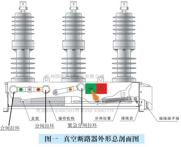
1.4.2 The circuit breaker adopts a three-phase strut structure, which has stable and reliable breaking performance, compact and reasonable overall structure, small volume and light weight. Long service life and other characteristics.
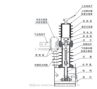
1.4.3 Vacuum interrupter: The breaking performance is stable and reliable, the contact wear is small, there is no danger of flammability and explosion, and safety can be maintenance-free.
1.4.4 Three-phase props and current transformers are made of high-quality outdoor silicone rubber solid insulation, which is resistant to high, low temperature, UV and aging.
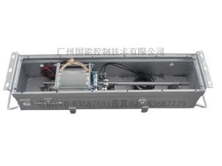
1.4.5 Circuit breaker adopts permanent magnet operating mechanism, with few parts, small size, maintenance-free, and mechanical life of more than 30,000 times. The operating mechanism is placed in a sealed housing to solve the problem of corrosion of the mechanism and improve the reliability and service life of the mechanism.
1.4.6 The opening and closing operation of the circuit breaker can be performed by manual and electric splitting and closing operations and providing a remote operation interface. It can be integrated with the controller to realize distribution automation, and can be combined with the demarcation controller to form a watchdog demarcation circuit breaker or recloser.
1.4.7 Circuit breaker AC phase is equipped with current transformer, and is equipped with outdoor voltage transformer for overcurrent automatic trip protection and information analysis with intelligent controller to achieve various protection functions.
1. 5 product model
NKZW32Y-12G 630A/1250A - 20/31.5
20/31.5 rated short circuit breaking current (kA)
630/1250 rated current (A)
Y permanent magnet operating mechanism
G isolation switch
12 highest working voltage (kV)
NKZW32Y design serial number outdoor permanent magnet vacuum circuit breaker
2. Technical parameters
2.1 The main technical parameters are shown in Table 1.
2.2 Mechanical characteristics are shown in Table 2.
2.3 Operating mechanism characteristics are shown in Table 3.
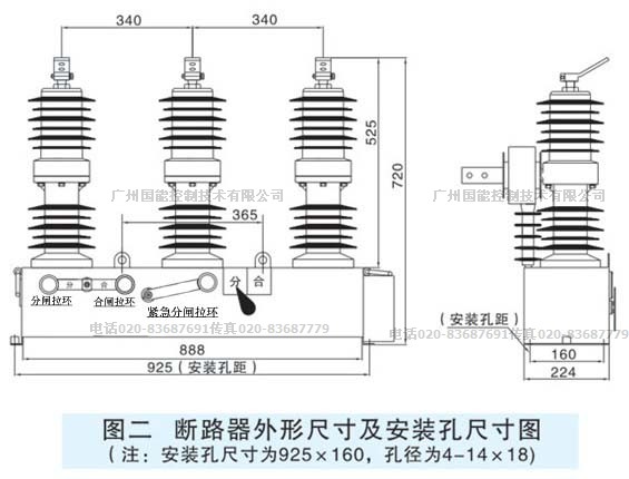
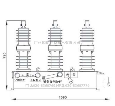
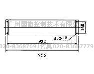
2.4 The external dimensions and installation dimensions of the circuit breaker are shown in Figure 1, Figure 2, Figure 3 and Figure 4.
3. Operating mechanism and its operating principle
3.1 manual mechanism action principle.
Table 1 main technical parameters of the circuit breaker
| RF |
Project
|
unit
|
Value
|
|
1
|
Rated voltage |
kV
|
12
|
|
2
|
Rated frequency |
Hz
|
50
|
|
3
|
Rated current |
A
|
630/(1250)
|
|
4
|
Rated short-circuit breaking current |
kA
|
20/(31.5)
|
|
5
|
Rated peak withstand current (peak) |
kA
|
50/(80)
|
|
6
|
Rated short circuit withstand current / duration |
kA/s
|
20/4 / (31.5/4)
|
|
7
|
Rated short circuit closing current (peak) |
kA
|
80
|
|
8
|
Rated operation sequence |
|
open -0.3s - close open - 180s - close open
|
|
9
|
Mechanical life |
Times
|
10000
|
|
10
|
Rated current breaking times |
Times
|
10000
|
|
11
|
Rated short-circuit breaking current breaking times |
Times
|
30
|
|
12
|
Power frequency withstand voltage (1min):
(wet) phase to ground
(dry) phase, ground/fracture
|
kV
|
34
42/49
|
|
13
|
Lightning impulse withstand voltage (peak) phase to ground, ground / fracture |
kV
|
75/85
|
|
14
|
Secondary circuit 1min power frequency withstand voltage |
V
|
2000
|
Table 2 main mechanical characteristics of the circuit breaker
| Serial number |
parameter name
|
unit
|
data
|
|
1
|
Contact opening distance |
Mm
|
9±1
|
|
2
|
Contact overtravel |
Mm
|
2.5±0.5
|
|
3
|
Opening speed |
m/s
|
1.2±0.2
|
|
4
|
Closing speed |
m/s
|
0.8±0.2
|
|
5
|
Contact closing bounce time |
Ms
|
≤2
|
|
6
|
Interphase center distance |
Mm
|
340±1.5
|
|
7
|
Three-phase switching |
Ms
|
≤2
|
|
8
|
Conductive loop resistance of each phase |
μΩ
|
≤80
|
|
9
|
Closing time |
Ms
|
25~60
|
|
10
|
Opening time |
Ms
|
18~45
|
|
11
|
Energy storage motor rated power |
w
|
40
|
Table 3 main technical parameters of the operating mechanism
|
Serial number
|
project
|
Test Conditions
|
data
|
|
1
|
Suitable for permanent magnet mechanism
|
Monostable
|
Single coil
|
|
2
|
Input operating voltage
|
DC screen AC with capacitor
|
AC220V
DC100-360V
|
|
3
|
Capacitor charging voltage
|
1 to 100,000 μF
|
DC210-280V or
DC95-150
|
|
4
|
Capacitor charging current
|
|
<3A
|
|
5
|
Static standby power consumption
|
|
≤3W
|
|
6
|
Closing gate maximum drive current
|
100ms
|
DC80A or DC160A
|
|
7
|
Secondary control power output
|
Load must be less than 20mA
|
DC24V20mA
|
|
8
|
Combination and opening alarm voltage
|
Adjustable separately
|
DC80-280V
|
|
9
|
Opening contact parameter
|
Normally open
|
0.5A125VAC
0.2A110DC
|
|
10
|
Use environment
|
|
—30°C to 70°C
|
|
11
|
way of communication
|
Isolated 485 bus
|
Remote signaling, parameter setting
|
|
12
|
Maximum size
|
Length * width * height
|
150*150*38
|
|
Note: The specific parameters are set according to the parameters of the switch.
|
3.1.1 Working principle:
When the switch is closed, the controller controls the external circuit to supply the drive current to the coil. The magnetic field generated by the coil current is in the same direction as the magnetic field generated by the permanent magnet, and is superimposed on each other. As the coil drive current increases, the drive force F generated by the magnetic field gradually changes. Large, when the driving force is greater than the opening holding force provided by the circuit breaker, the moving iron core follows Newton's law: F=ma moves downward, and the driving force increases sharply as the magnetic gap decreases, eventually pushing the moving iron core to Closing position.
At this time, the controller cuts off the coil power supply according to the protection time set by the program. Since the ferromagnetic circuit has been closed at this time, the magnetic force of the permanent magnet has satisfied the closing force of the circuit breaker, so that the circuit breaker is in the closed state.
When opening, a small current is applied to the coil, and the magnetic field generated by the current is opposite to the direction of the magnetic field generated by the permanent magnet, which weakens the magnetic field of the ferromagnetic circuit. When the magnetic force is smaller than the closing holding force of the circuit breaker, the combined force pushing mechanism of the circuit breaker The moving iron core moves in the direction of opening and completes the opening process.
3.2 quick disconnect, overcurrent protection controller, dial switch setting diagram
Note: The controller cannot be quit protected under normal use.
Note: If the controller needs to exit the protection, the following operations must be performed when the circuit breaker is opened (no current flows on the primary side).
Remove the short wire (A phase change ratio line) of BH4-BH8 and change it to BH4-BH1.
Remove the short wire (C phase change ratio line) of HC1-BH7 and change it to HC1-BH1.
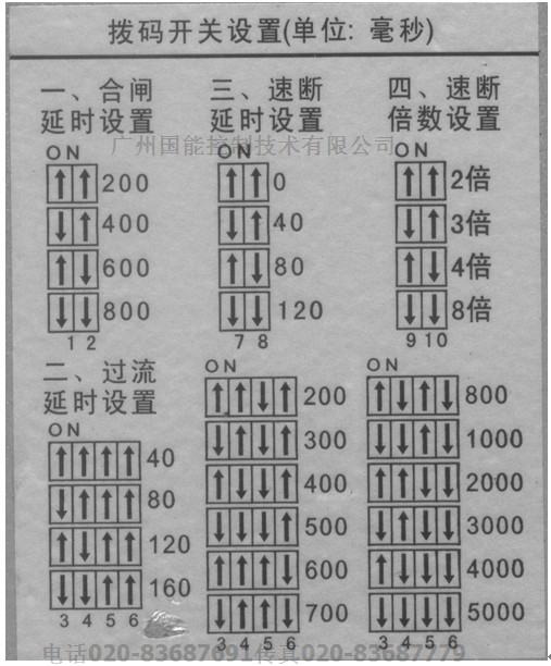
NKZW32Y-12/ 630/1250A-20/31.5 outdoor high voltage permanent magnet column circuit breaker
The rated primary current is 630A/1250A, the overcurrent setting is the primary current 630A/1250A, and the quick-break multiple setting is a multiple of the primary current 630A/1250A.
The closing delay setting is recommended for 800ms.
3.3 wiring diagram
4. Isolation switch ( this function is not available in this unit )
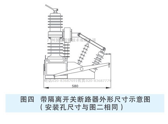
4.1 For users who need to install isolation switch, NKZW32-12G series switch can be used. The external dimensions and structure are shown in Figure 1 and Figure 2. The isolating switch is bolted to the mechanism box of the NKZW32-12 circuit breaker. It is rugged, stable, easy to disassemble and reliable, and can be flexibly installed.
4.2 The main technical parameters of the isolating switch are shown in Table 3.
|
Serial number
|
Project
|
unit
|
parameter
|
|
1
|
Rated voltage |
kV
|
12
|
|
2
|
Rated current |
A
|
630/1250
|
|
3
|
4s rated short-time withstand current (RMS) |
kA
|
16, 20/31.5
|
|
4
|
Rated peak withstand current |
40, 50/80
|
|
5
|
1min power frequency withstand voltage |
Ground, phase |
kV
|
42
|
| Fracture |
48
|
|
6
|
Loop resistance (breaker wiring board to isolation switch between the board) |
μΩ
|
≤100
|
|
7
|
Center yaw amount when three-phase knife shutter is closed |
Mm
|
≤2
|
|
8
|
Three-phase knife gate division and closing synchronization deviation |
≤2
|
|
9
|
Conductive part to ground insulation distance |
≥160
|
|
10
|
Fracture opening |
≥200
|
|
11
|
weight |
Kg
|
≤40
|
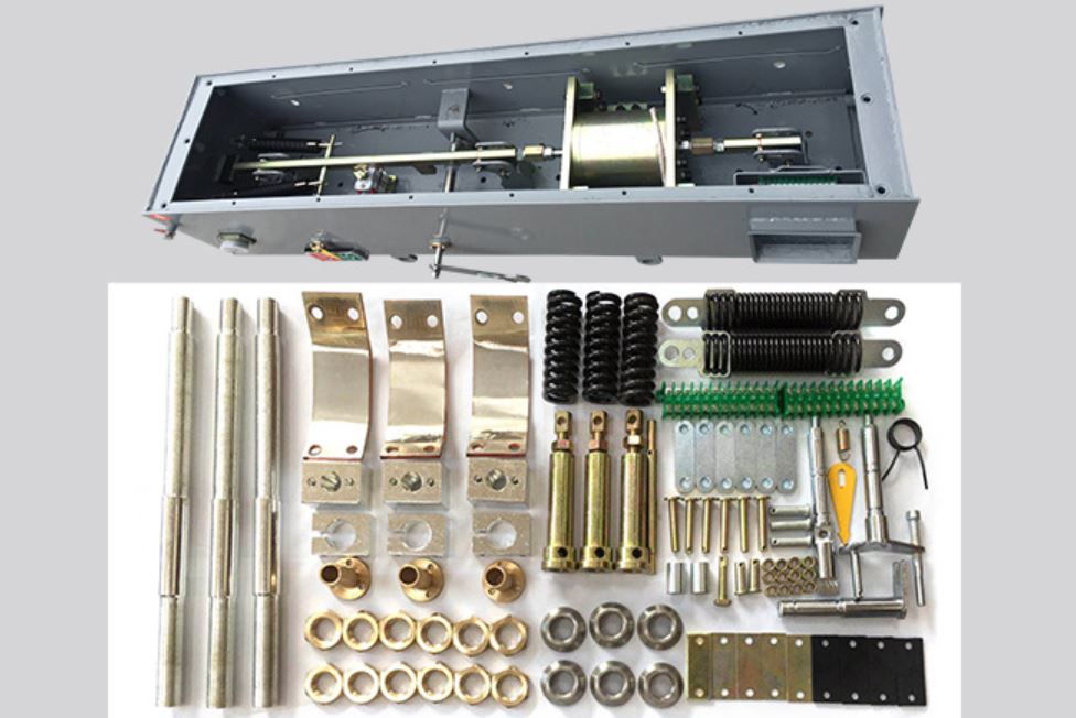
4.3 isolation switch structure features
The isolating switch is composed of an isolating frame 12, an insulator 7, an insulating rod 11, a blade 10, an isolating main shaft 2, an inlet board 9, an operating handle 1, a current transformer 8, and the like. The isolation bracket is fixed on the mechanism box, and the terminal of the circuit breaker is used as a fulcrum of the knives to form one end of the isolation fracture. The other end of the fracture opening and closing the knife gate by operating the insulator and the drive shaft. The three-phase linkage has obvious visible fractures in the state of opening of the isolating switch, and has a reliable anti-error mechanism interlocking with the main body of the circuit breaker, which is convenient and safe to maintain.
4.4 isolation switch operation sequence
4.4.1 Closing operation (power transmission operation)
a) Pull the isolation switch operating handle, close the isolation knife, and close it in place;
b) Pull the circuit breaker energy storage handle (the motoring mechanism is closed);
c) Pull down the circuit breaker closing pull ring and close the circuit breaker (the motor mechanism does not have this step).
4.4.2 Opening operation (manual power failure, maintenance operation)
a) Pull down the circuit breaker opening pull ring and open the circuit breaker;
b) Check the outlet side of the circuit breaker and confirm that there is no electricity.
c) Pull the isolation switch operating handle, open the isolation knife and open it in place.
4.4.3 Notes
a) It is strictly forbidden to separate the disconnecting switch when the circuit breaker is closed;
b) The isolating switch must be in place, otherwise the circuit breaker must not be opened or closed.
c) Before the manual opening, it must be confirmed that there is no electricity on the outlet side of the circuit breaker.
5. Transportation, commissioning and installation
5.1 The product shall not be turned over or inverted during transportation, and anti-seismic measures shall be taken. When lifting the circuit breaker, the four earrings on the box must be hooked up. Do not carry the epoxy insulation sleeve directly.
5.2 After unpacking, check whether the outdoor epoxy insulation sleeve of the circuit breaker on the column is broken, whether the box is deformed, whether the indication is complete, whether the product nameplate and certificate are consistent with the order form, and whether the packing list is consistent with the physical object.
5.3 Before the circuit breaker is put into operation, it should be carefully checked whether the rated voltage and rated current of each operating component are consistent with the actual conditions.
5.4 The contact parameters and mechanical characteristics of the circuit breaker have been adjusted at the factory inspection, and the user does not have to open the box for inspection. After the pressure test is carried out as required, it can be installed. It is possible to perform mechanical property inspection in accordance with the requirements of Table 2.
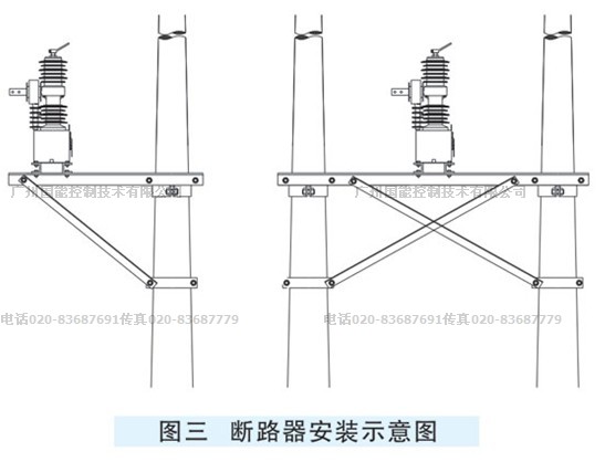
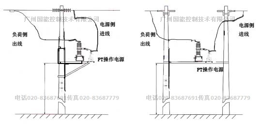
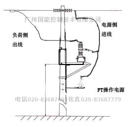
5.5 The circuit breaker can be erected on a single pole or double pole. The circuit breaker should be installed smoothly and firmly on the special steel frame (as shown in Figure 3).
Preparation before installation:
1Golding processing
According to the selected installation method, the installation and installation of the fittings and the external PT brackets, and the detailed processing of the fittings of the fittings are installed.
2 Preparing the installation accessories The
following are the number of accessories required for a single device:
1) 6 high-voltage arresters (3 on the power supply side and load side)
2) 10KV insulators (specification and quantity depending on the installation method and the size of the pole) ;
3) hoop (based on size and number and size of installation pole may be);
4) connected to a switch line clamp 6 (specific dimensions of the line field diameter may be);
5) the ground wire.
6) PT bracket.
3 Check the
appearance of the equipment to be inspected:
1) Is the fastening and sealing intact?
2) Is the casing and the casing damaged?
3) Is the control socket and the pin intact?
4) Is the operating handle and the split pointer normal? Position? Insulation measurement content: 1) Insulation resistance: once to the second and ground: ≥ 10000MQ; secondary to ground: ≥ 10MQ 2) Insulation withstand voltage: once to the second and ground: 42KV, 1min; 2KV, 1min;
Installation steps
Step 1: Install the circuit breaker bracket and install the PT bracket.
Step 2:
Place the switch in the opening position before lifting and lifting;
Note:
* The length of the wire hooked on the hook should be 0.8m;
* Pay attention to the protection switch during the lifting process to avoid damage to the casing and casing. ;
* The switch allows for a slight tilt.
Step 3: After
lifting the circuit breaker to a position slightly higher than the horizontal crossbar of the mounting bracket, place the circuit breaker on the horizontal cross arm of the mounting bracket and fasten it with four sets of M12x60 stainless steel bolts and nuts. After confirming that the fixing is in good condition, untie the lifting wire.
Place the external PT on the lower PT mounting bracket of the circuit breaker and fasten it with 4 sets of M14x40 stainless steel bolts and nuts.
Step 4: Connection of the primary cable
1) When the isolation switch is not required to be installed on the primary line, the outlets on both sides of the circuit breaker can be directly connected to the line by the clamp. If the isolation switch is required to be installed on the primary line, the copper terminal is used. Connect the line to the exit side of the isolation knife gate.
2) Use two insulated high-voltage wires of about 10 square inches or more to connect the AB phase on the power supply side, and the other end to the high-voltage side terminal of the PT.
Note:
* Note that the insulation spacing between the cables of each phase is at least 100mm. the above;
*The circuit breaker is not less than 6.5 meters from the ground. *The distance between the PT and the circuit breaker is not less than 1.5 meters.
* Be sure to install lightning arresters on both sides of each phase of the switch to prevent lightning damage to the equipment.
*If the controller is not less than 2.5 meters from the ground
6. Product maintenance and maintenance
6.1 The circuit breaker on this column ensures the user's medium and long-term maintenance-free operation due to its special design structure. It only needs to perform the power frequency withstand voltage test every three years or so.
6.2 Users are not allowed to replace the electrical components that are inconsistent with the original model specifications.
6.3 The operator should have a preliminary understanding of the performance of the organization and the knowledge of installation adjustment and maintenance. The problems in operation should be recorded and the manufacturer should be notified if necessary.
7. Random files
7.1 One product certificate.
7.2 Install a copy of the instruction manual.
7.3 One packing list.
7.4 A copy of the factory inspection report.
8. Ordering Information
When ordering, please specify the model, name, quantity, rated current, rated breaking current, current transformer current ratio, operating mode and operating voltage.
9 . Notes
9.1 It is strictly forbidden to reverse the polarity of the DC screen power supply and the capacitive storage capacity, or directly short-circuit the output of the opening and closing coil or connect with the positive and negative terminals of the operating power supply. Otherwise, the controller will be damaged and all consequences will be responsible for it.
9.2 It is strictly forbidden to use the output power of the controller to supply power to other electrical equipment.
9.3 The controller connection must be reliable, especially the opening and closing coil leads, otherwise it is easy to start the arc and damage the controller.
9.4 When using the storage capacitor, the AC220V power input must be connected to the current limiting resistor or reactor to charge the capacitor.
9.5 Directly use DC screen power supply, connect the positive and negative poles of the power supply directly to the corresponding input terminals of the original storage capacitor.
9.6 The controller does a long-term closing test. It is recommended that no more than three points per minute.
9.7 This controller is a precision electronic product. It is strictly forbidden to disassemble it by yourself. If there is any problem, return it to our company for processing.
9.8 As the technology advances and the power distribution requirements are improved and improved, there will be improvements and differences in the future specifications. The improved content will be subject to change without prior notice.
|
Delivery date
|
location
|
|
project name
|
Project Number
|
|
product name
|
Outdoor high voltage permanent magnet column vacuum circuit breaker
|
|
Product number
|
NKZW32Y-12 630A/1250A--20/31.5
|
|
Rated voltage
|
10KV
|
|
Rated current
|
630A/1250A
|
|
Breaking short circuit current (4S)
|
20KA/31.5KA
|
|
Close short circuit current (4S)
|
50KA/80KA
|
|
Operating mechanism
|
Permanent magnet
|
|
Number of PT
|
Outdoor type 1 AC 220V / 50Hz
|
|
Current transformer ratio
|
Shell outer phase CT600:5 (10P20),
|
|
Switch housing
|
stainless steel
|
|
PT and switch (2.5 square) cable length
|
5 meters
|
|
Altitude
|
1km
|
|
Controller position
|
Built in
|
|
Controller function
|
Over-current cut-off protection closing delay
|
|
way of communication
|
no
|
|
LCD remote control
|
no
|
|
Small remote control
|
Have
|
|
Neutral grounding method
|
Ungrounded
|
|
Load side capacity
|
12500kVA
|
Installation diagram
*The circuit breaker is not less than 6.5 meters from the ground. *The distance between the PT and the circuit breaker is not less than 1.5 meters.
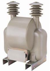
YZW-10 outdoor type power supply transformer
1 Model meaning
This product is a special transformer for the operation of the circuit breaker operating mechanism.
2 Technical parameters
Model YZW-10 rated primary voltage 10KV (line voltage) rated secondary voltage (0.11 or 0.22KV) capacity (1000VA) weight 45KG
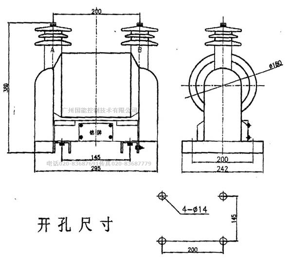
3 shape and installation dimensions are shown in
Creepage distance 580mm
It is recommended that the NKZW32 permanent magnet vacuum circuit breaker and PT installation spacing be greater than 580mm
********************
The characteristic parameters of the permanent magnet mechanism are related to the adapted circuit breaker, in particular the parameters of the vacuum interrupter. Different series of vacuum interrupters have different requirements for opening and closing speed, mechanical life, contact pressure, opening distance, overtravel, bounce, and different periods . Correspondingly, it is necessary to optimize the permanent magnet mechanism. Designed to meet the requirements of the arc chamber. Therefore, for the user, the selection of the permanent magnet mechanism is not the greater the retention force, the faster the better, the faster the speed, the lower the life of the vacuum interrupter on the one hand, and the increased operating current on the other hand. At the cost, the reliability of the control part is degraded.
The following table is the relevant parameters of NKZW32-12/630-20 permanent magnet mechanism designed by our company.
NKZW32 permanent magnet mechanism outline drawing
|
|
| |
|
|
|
|
|
|
|