NK3S智能永磁三相同步合闸断路器] 分相控制智能永磁断路器
NK3S intelligent three-phase permanent magnet synchronous closing breaker] phase control of intelligent permanent magnetic circuit breaker
My company's permanent magnetic circuit breaker because very few moving parts, cancelled the mechanical locking and tripping of the complex system, so it has irreplaceable advantages: less failure, reliable, long life (up to 30000 times above), no need of lubrication, has wide power supply, coal, smelting steel, railway etc..
By our company independently developed YCK380 series permanent magnet switch controller, and cooperate with our company's permanent magnetic actuator, can realize the circuit breaker switching operations, over current protection, watchdog protection, wireless remote control operation, reclosure, and distribution automation functions, make the switch become intelligent circuit breaker maintenance free the.
The "people-oriented, winning with quality" is the company's operating philosophy, "a leading science and technology, customer service" for business purposes, to "attaches great importance to product quality, professional spirit, firm and indomitable, team cooperation" as the enterprise spirit. The company will always take the market as the guidance, take the customer demand as the center, struggling to forge ahead, strive to explore the development, production of new and high technology products, the more the better, for the majority of customer service.
1 NK3S intelligent permanent magnetic circuit breaker Product Overview: three-phase independent permanent magnetic actuator drive phase control of intelligent permanent magnetic circuit breaker
The 1.1 main purposes
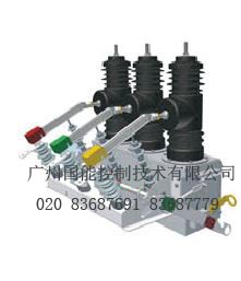
NK3S outdoor high voltage permanent magnetic vacuum circuit breaker (hereinafter referred to as the circuit breaker) is the highest rated voltage 12/24kV, three-phase AC 50Hz outdoor distribution equipment. Mainly used for distribution network interruption, closing in the power system load current, overload current and short-circuit current. Applied to substation and industrial and mining enterprises in distribution systems for protection and control purposes, more suitable for rural power grid and the frequent operation place needs, especially suitable for city network, rural power network transformation.
The installation instructions provided the main technical parameters, circuit breaker product structure, operation, installation, use and maintenance of the principle and the method of content.
1.2 normative references
AC high voltage circuit breaker "GB1984-2003"
Common technical requirements of high voltage switch equipment and control equipment of the "GB/T11022-1999" standard
GB311.1-1997 "insulation coordination of high voltage transmission and transformation equipment: high voltage test technique"
GB3309-1989 "mechanical testing of high voltage switch equipment at room temperature"
DL/T403-2000 "12~40.5kV high voltage vacuum circuit breaker order technical conditions"
1.3 the use of environmental conditions
1.3.1 elevation not exceeding 2000 meters;
1.3.2 ambient air temperature: -45 degrees ~+40 degrees;
1.3.3 wind speed less than 35m/s;
1.3.4 contamination grade: IV
1.3.5 mounting ambicnt: no flammable, explosive and dangerous, chemical corrosion.
1.3.6 seismic intensity does not exceed 8 degrees
The 1.4 main features
1.4.1 full sealed structure: good sealing performance, help to improve the moisture-proof, anti condensation performance, suitable for hot and humid areas to use, effectively avoid switch mechanical corrosion caused by long-term outdoor environment.
1.4.2 circuit breaker adopts three-phase pillar type structure, with the breaking performance is stable and reliable, compact integral structure, small volume, light weight and reasonable. The use of long life and other characteristics.
1.4.3 vacuum interrupter: breaking performance is stable and reliable, small wear contacts, non flammable and explosive dangerous, safety and maintenance free.
1.4.4 three-phase pillar and current transformer using high-quality outdoor silicone rubber solid insulation, with high and low temperature resistance, ultraviolet resistance, aging resistance characteristics.
1.4.5 circuit breaker with permanent magnetic operating mechanism, few parts, small volume, maintenance free, mechanical service life more than 30000 times. The operating mechanism is arranged in the sealed shell, solves the mechanism of corrosion problems, improve the reliability and service life of mechanism.
The opening operation of 1.4.6 circuit breaker can adopt manual and electric points, closing operation and provide remote operation interface. With the controller supporting implementation of distribution automation, and boundary controller watchdog demarcation circuit breaker or recloser.
1.4.7 circuit breaker ABC is respectively provided with a current mutual inductor, and is equipped with outdoor voltage transformer, providing overcurrent automatic tripping protection and corresponding with the intelligent controller, information analysis, to achieve a variety of protection function.
1.5 types of products
NK3S-12G 630A/1250A - 20/31.5
20/31.5 rated short-circuit breaking current (kA)
630/1250 rated current (A)
G isolation switch
12/24 maximum working voltage (kV)
NK3S driver design number three phase independent of permanent magnetic actuator
2 technical parameters
2.1 main technical parameters are shown in Table 1
2.2 mechanical properties are shown in Table 2
2.3 operating mechanism characteristics are shown in Table 3
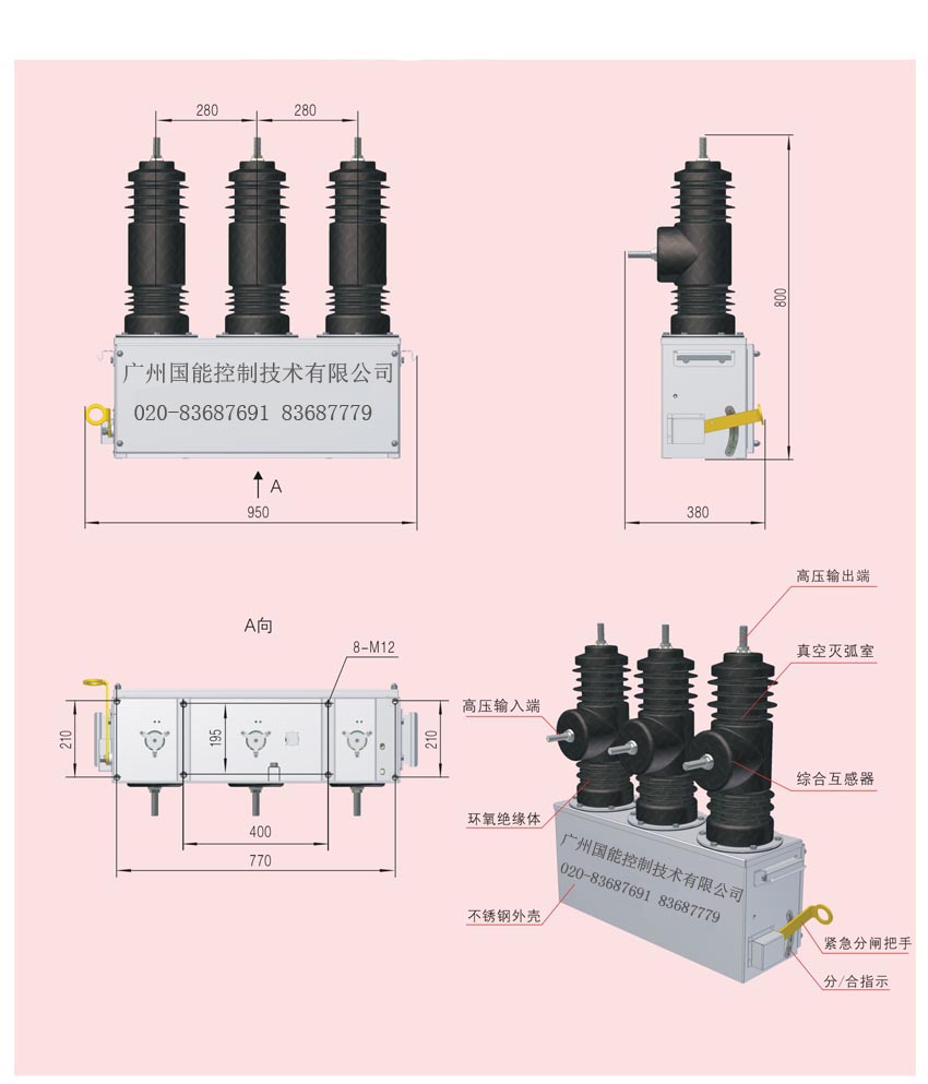
The 2.4 circuit breaker outline dimensions and mounting dimensions of Figure 1, figure 2, figure 3, figure 4.
And the action principle of 3 operating mechanism
The action principle of 3.1 manual organ.
Main technical parameters of the 1 circuit breaker
Serial number
Project
Unit
The number of values
1
Rated voltage KV 12 2
Rated frequency Hz 50 3
Rated current A
630/ (1250)
4
Rated short-circuit breaking current
KA
20/ (31.5)
5
Rated peak withstand current (peak)
KA
50/ (80)
6
Rated short-time withstand current / duration
KA/s
20/4 / (31.5/4)
7
Rated short-circuit current (peak)
KA
80
8
Rated operating sequence
-0.3s- -180s- he divided into
9
Mechanical life
Time
10000
10
Breaking times of rated current
Time
10000
11
Breaking current rated short-circuit breaking times
Time
30
12
Power frequency withstand voltage (1min):
(wet) phase to ground
(dry) phase, the ground / fracture
KV
34
42/49
13
The lightning impulse withstand voltage (peak) phase, the ground / fracture
KV
75/85
14
The two loop 1min power frequency withstand voltage
V
2000
Table 2 the main mechanical characteristics of circuit breaker
4 isolation switch (optional)
4.1 for the need for the installation of isolation switch user, can choose NK3S-12G series switch, size and structure shown in Figure 1, figure two. Isolating switch mechanism box is fixed on the NK3S-12 circuit breaker with bolt, strong, stable, convenient disassembly, reliable, flexible installation.
The main technical parameters of 4.2 isolating switch, see Table 3
Serial number
Project
Unit
Parameters
1
Rated voltage
KV
12
2
Rated current
A
630/1250
3
4S rated short-time withstand current (effective value)
KA
16, 20/31.5
4
Rated peak withstand current
40, 50/80
5
1min power frequency withstand voltage
On the ground, and white
KV
42
Fracture
48
6
Loop resistance (circuit breaker wiring board to the isolation switch into the board room)
Omega
Less than or equal to 100
7
The three-phase knife switch switching center deflection
Mm
Less than or equal to 2
8
The three-phase knife switch points, closing simultaneity bias
Less than or equal to 2
9
The ground insulation distance conductive part
More than 160
10
Fracture opening distance
More than 200
11
Weight
Kg
Less than or equal to 40
The structure characteristics of the 4.3 isolating switch
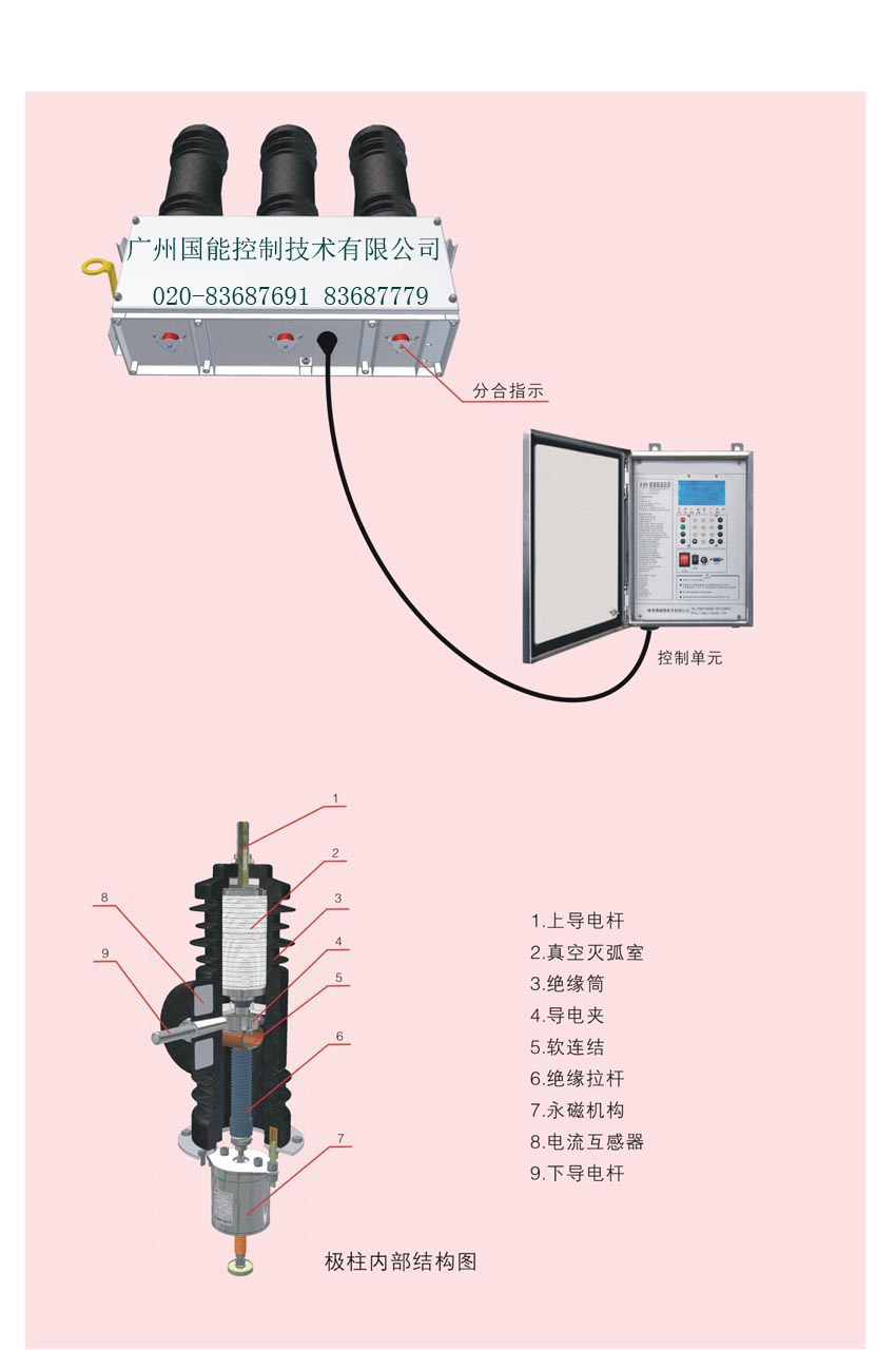
Isolation switch insulator by isolation frame 12, 7, 11, 10, the insulating rod blade isolation spindle 2, board 9, an operating handle 1, a current transformer 8 etc.. The isolating bracket fixed on the mechanism box, use the terminal circuit breaker as the knife pivot, constitute the end of isolation fracture, the other end fracture closing knife switch through the operating insulator and a drive shaft to open. Three-phase linkage, in isolating switch has a visible fracture obviously divided brake state, reliable anti misoperation interlocking between the institutions, and with the circuit breaker body and convenient maintenance, safety.
Operation of the order of 4.4 isolation switch
4.4.1 closing operation (operation electricity)
Pull a) isolating switch operation handle, closed the isolation knife, closed in place;
B) pull circuit breaker energy storage handle (motor mechanism is closing);
C) pull down the circuit breaker closing ring, the breaker (motor mechanism without this step).
4.4.2 brake operations (manual power, maintenance and operation)
A) pull down the gate ring circuit breaker, circuit breaker;
B) circuit breaker outlet side electrical inspection, confirmed no electricity.
Pull C) isolating switch operation handle, open the isolation knife, opened in place.
The 4.4.3 notes
A) is strictly prohibited in the circuit breaker closing, separated switch;
B) isolating switch must be divided in place, otherwise the circuit breaker shall carry out switching operations.
C) must confirm the outgoing side of circuit breaker without electric hand-operated gate before.
5 transportation, installation and debugging
5.1 products shall not be overturned and inverted in the transport process, and to take precautions against earthquakes. Lifting circuit breakers, must hook the four earring box on the hoist. Not directly handling epoxy insulating sleeve.
5.2 out of the box should be checked after the column circuit breaker outdoor epoxy insulating sleeve has no rupture, the box body is deformed, division instructions is complete, the product nameplate, certificate is consistent with the order form, packing list is consistent with the physical.
The 5.3 column circuit breaker is put into operation, the operation should be carefully checked element of rated voltage and current with the actual situation is consistent.
The contact parameters and mechanical parameters of the 5.4 circuit breaker in the factory inspection has been adjusted, the user does not need to check out of the box. Voltage test according to the requirements, can be installed. The conditions can mechanical properties examination in accordance with the requirements of table 2.
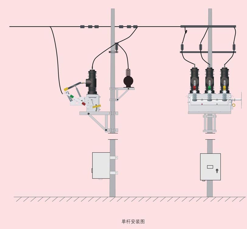
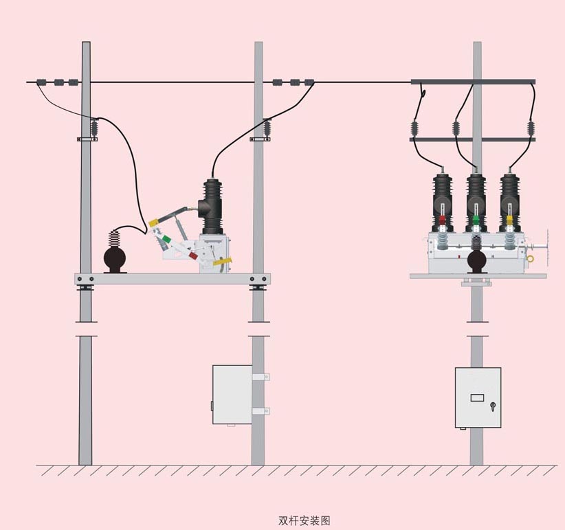
The 5.5 circuit breaker can be single rod is installed, can also double poles. The circuit breaker should be stable, firmly installed in special steel frame (Fig. three)
Preparation before installation work:
1 fittings processing
According to installation mode selected processing installation fittings and external PT bracket, mounting hardware accessories with processing size chart.
2 prepare installation accessories
The following is the number of single equipment required accessories:
1) high voltage arrester 6 (power supply side and the load side of the 3)
10KV insulator (2) size installation mode and poles according to specifications and quantity);
Hoop (3) size installation mode and poles according to specifications and quantity);
4) switch outlet connecting clamp 6 (specific dimensions on the basis of field line size and decide);
5) the grounding conductor.
6) PT stent.
3 for equipment check
The content of visual inspection:
1) fastening and sealing is good?
2) casing and casing for any damage?
3) control socket and pin is intact?
4) the operating handle and divided the pointer is in the normal position?
Determination of content of insulation:
1) insulation resistance: one to two times and two times greater than or equal to: 10000MQ; on the ground: greater than or equal to 10MQ
2) insulation: one to two times and two times: 42KV, 1min; 2KV, 1min: on the ground;
Installation steps
The first step: the circuit breaker installed bracket, bracket and install PT.
The second step: Lifting
Before lifting the switch in the off position;
The matters needing attention:
* is hooked in the hook on the cord length should be 0.8m;
* the lifting process should pay attention to the protection of switch do not collide to avoid hurting the casing and casing;
* switch to allow slightly inclined.
The third step: fixed
The circuit breaker is lifted to the mounting frame level than the cross arm slightly elevated position, the circuit breaker is placed on the mounting frame level cross arm, and fasten with stainless steel bolts and nuts four group M12x60. Confirm the fixed intact, untie the lifting rope.
The external PT circuit breaker PT in lower part of the mounting rack, with stainless steel bolts in 4 of M14x40 group, the fastening nut.
The fourth step: to connect a cable
1) when a line do not need to install the isolation switch, can be directly used clamp circuit breaker outlet is connected with both sides of the line, if a line needs to install the isolation knife brake, will the line and the isolation knife outlet side is connected using a copper terminal.
2) with two more than about 10 square insulated high-voltage wire end is connected to the supply side of the AB phase, another head and connected to the high side PT wiring terminal.
The matters needing attention:
* note that the insulating spacing between each phase cable stay at least more than 100mm;
* spacing breaker from the ground of not less than 6.5 m *PT circuit breaker with not less than 1.5 metres
* Please be sure to switch each phase on both sides of the installation of lightning arrester to prevent damage to the equipment of lightning.
* if the controller is not less than 2.5 metres from the ground
Overhaul and maintenance of 6 products
The 6.1 column circuit breaker because of its special structure design to ensure that the user use long-term maintenance free, only every three years or so a power frequency withstand voltage test.
6.2 users may not replace the use of electrical components were not consistent with the specifications of raw types of casual.
6.3 operating personnel should understand the initial maintenance knowledge and installation and adjustment, mechanism of operation performance in question shall be recorded, when necessary, notify the manufacturer.
7 random file
7.1 products a certificate.
7.2 installation manual a.
7.3 packing list in one.
7.4 factory inspection report.
8 notice
When ordering to description of product model, name, quantity, rated current, rated breaking current, with the current of the current transformer ratio, mode of operation and the operational voltage.
9 note
9.1 it is strictly prohibited to DC panel power supply polarity and the energy storage capacitor of reverse connection, or will be closing coil output direct short circuit or and operation power of positive and negative connection, otherwise it will make the controller damage, all consequences are responsible for.
9.2 it is strictly prohibited to use the controller output power for other electrical equipment power supply.
The 9.3 controller connection must be reliable, especially switching coil lead wire, otherwise easy to arc damage controller.
9.4 with the energy storage capacitor is used, the AC220V power input must be connected in series with the current limiting resistor and reactor for capacitor charging.
9.5 the direct use of DC panel power supply, the corresponding input will power supply positive and negative poles with the original energy storage capacitor terminal directly connected.
The 9.6 controller do long time closing opening test, recommends every minutes of no more than three points.
The 9.7 controller is a precision electronic products, prohibited the disassembly, if there are questions, back to my company processing.
9.8 with the advancement of technology and distribution improvement and demands, there is improvement and the difference in the future in the specification, then to the improved content shall prevail, without notice.
Delivery date
Place
Project name
Project number
Product name
Outdoor high voltage permanent magnetic column vacuum circuit breaker
The product model
NK3S-12 630A/1250A--20/31.5
Rated voltage
10KV
Rated current
630A/1250A
Breaking short circuit current (4S)
20KA/31.5KA
Close short circuit current (4S)
50KA/80KA
The operating mechanism
Permanent magnet
The number of PT
Outdoor type 1 AC 220V / 50Hz
Current transformer ratio
Shell type phase CT400:5 (10P20),
The switch casing
Stainless steel
PT and the switch (2.5 square feet) of cable length
7 meters
High altitude
1km
The position controller
The built-in
The function of the controller
Over current quick break protection
Communication mode
No
LCD remote control
No
The small remote control
There are
Neutral point grounding mode
Not grounded.
The load side capacity
1250kVA
我公司的永磁断路器由于运动部件非常少,取消了复杂的机械锁扣及脱扣系统,因而具有无法替代的优势:故障少、可靠、寿命长(可达到3万次以上)、无需润滑,目前已广泛供电、煤矿、炼钢、铁路等。
由我公司自主研发的YCK380系列永磁开关控制器,及配合我公司的永磁操动机构,可以实现断路器的分合闸操作、过流速断保护、看门狗保护、无线遥控操作、重合闸操作,以及配网自动化功能等,使开关成为免维护的智能断路器。
“以人为本,以质取胜”是公司的经营理念,以“领先科技,服务客户”为企业经营宗旨,以“高度重视产品质量,专业进取,坚韧不拔,团队合作”为企业精神。公司将始终以市场为导向,以客户需求为中心,奋力进取,努力开拓开发,生产更多、更好的高新技术产品,为广大用户服务。
1. NK3S智能永磁断路器 产品概述 --三相独立永磁机构驱动 分相控制智能永磁断路器
1.1主要用途
NK3S 型户外高压永磁真空断路器(以下简称断路器)是最高额定电压为12/24kV,50Hz三相交流的户外配电设备。主要用于配电网开断、关合电力系统中的负荷电流、过载电流及短路电流。适用于变电站及工矿企业配电系统中作保护和控制之用,更适用于农村电网及频繁操作的场所,特别适用于城网、农网改造的需要。
本安装使用说明书规定了断路器的主要技术参数、产品结构、以及操作、安装、使用维护的原理和方法等内容。
1.2引用标准
GB1984-2003 《交流高压断路器》
GB/T11022-1999 《高压开关设备和控制设备标准的共用技术要求》
GB311.1-1997 《高压输变电设备的绝缘配合:高压试验技术》
GB3309-1989 《高压开关设备在常温下的机械试验》
DL/T403-2000 《12~40.5kV高压真空断路器订货技术条件》
1.3使用的环境条件
1.3.1海拔高度不超过2000米;
1.3.2周围空气温度:-45℃~+40℃;
1.3.3风速不大于35m/s;
1.3.4污秽等级:IV级
1.3.5安装场所:无易燃、爆炸危险、化学腐蚀的场所。
1.3.6地震强度不超过8度
1.4主要特点
1.4.1全密封结构:密封性能好,有助于提高防潮、防凝露性能,适应于高温潮湿地区使用,有效地避免开关因长期户外环境下而引起的机械锈蚀。
1.4.2断路器采用三相支柱式结构,具有开断性能稳定可靠,整体结构紧凑合理、体积小、重量轻。使用寿命长等特点。
1.4.3真空灭弧室:开断性能稳定可靠,触头磨损小,无易燃和爆炸危险、安全可免维护。
1.4.4三相支柱及电流互感器采用优质户外硅橡胶固体绝缘,具有耐高、低温,耐紫外线、耐老化的特点。
1.4.5断路器采用永磁操作机构,零部件少、体积小、免维护、机械寿命达3万次以上。操作机构置于密封的壳体中,解决了机构锈蚀的问题,提高了机构的可靠性和使用寿命。
1.4.6断路器的分闸操作可采用手动与电动分、合闸操作并提供远方操作接口。可与控制器配套实现配电自动化,可与分界控制器组成看门狗分界断路器或重合器.
1.4.7断路器ABC相各装有电流互感器,并装有户外电压互感器,供过电流自动脱扣保护并与智能控制器配套进行信息分析,以实现各种保护功能。
1. 5产品型号
NK3S-12G 630A/1250A - 20/31.5
20/31.5额定短路开断电流(kA)
630/1250额定电流(A)
G隔离开关
12/24最高工作电压(kV)
NK3S 设计序号 三相独立永磁机构驱动
2.技术参数
2.1主要技术参数见表1.
2.2机械特性见表2.
2.3操作机构特性见表3.
2.4断路器外形尺寸及安装尺寸见图1、 图2、图3、图4。
3.操作机构及其动作原理
3.1手动机构动作原理.
表1断路器主要技术参数
|
序号
|
项 目
|
单位
|
数 值
|
|
1
|
额定电压
|
kV
|
12
|
|
2
|
额定频率
|
Hz
|
50
|
|
3
|
额定电流
|
A
|
630/(1250)
|
|
4
|
额定短路开断电流
|
kA
|
20/(31.5)
|
|
5
|
额定峰值耐受电流(峰值)
|
kA
|
50/(80)
|
|
6
|
额定短路耐受电流/持续时间
|
kA/s
|
20/4 /(31.5/4)
|
|
7
|
额定短路关合电流(峰值)
|
kA
|
80
|
|
8
|
额定操作顺序
|
|
分-0.3s-合分-180s-合分
|
|
9
|
机械寿命
|
次
|
10000
|
|
10
|
额定电流开断次数
|
次
|
10000
|
|
11
|
额定短路开断电流开断次数
|
次
|
30
|
|
12
|
工频耐压(1min):
(湿)相间对地
(干)相间、对地/断口
|
kV
|
34
42/49
|
|
13
|
雷电冲击耐受电压(峰值)相间、对地/断口
|
kV
|
75/85
|
|
14
|
二次回路1min工频耐压
|
V
|
2000
|
表2断路器主要机械特性
|
序号
|
参数名称
|
单位
|
数据
|
|
1
|
触头开距
|
mm
|
11±1
|
|
2
|
触头超行程
|
mm
|
3±0.5
|
|
3
|
平均合闸速度
|
m/s
|
0.6±0.2
|
|
4
|
平均分闸速度
|
m/s
|
1.0~1.4
|
|
5
|
触头合闸弹跳时间
|
ms
|
≤2
|
|
6
|
相间中心距离
|
mm
|
280±2
|
|
7
|
三相分合闸不同期性
|
ms
|
≤2
|
|
8
|
各相导电回路电阻
|
µΩ
|
≤80
|
|
9
|
合闸时间
|
ms
|
30~50
|
|
10
|
分闸时间
|
ms
|
30~70
|
3.1.1工作原理:
合闸时,控制器控制外部电路向线圈提供驱动电流,线圈电流产生的磁场与永久磁铁产生的磁场方向一致,相互叠加,随着线圈驱动电流的不断增大,磁场产生的驱动力F逐渐变大,当驱动力大于断路器提供的分闸保持力时,动铁心按照牛顿定律:F=ma向下运动,并且驱动力随着磁隙的减小而急剧增大,最终将动铁心推到合闸位置。
此时控制器按程序设定的保护时间,切断线圈电源。由于此时铁磁回路已经闭合,永磁体的磁场力已满足断路器的合闸力,从而使断路器处于合闸状态。
分闸时,向线圈施加一个小电流,该电流产生的磁场与永磁体产生的磁场方向相反,削弱了铁磁回路的磁场,当磁力小于断路器的合闸保持力时,断路器合力推动机构动铁心向分闸方向运动,完成分闸过程。
本开关采用同步关合技术,实现断路器同步关合,有效抑制操作过电压和涌流 ,
特别适用于电容器的操作
3.3接线图
4.隔离开关(可选)
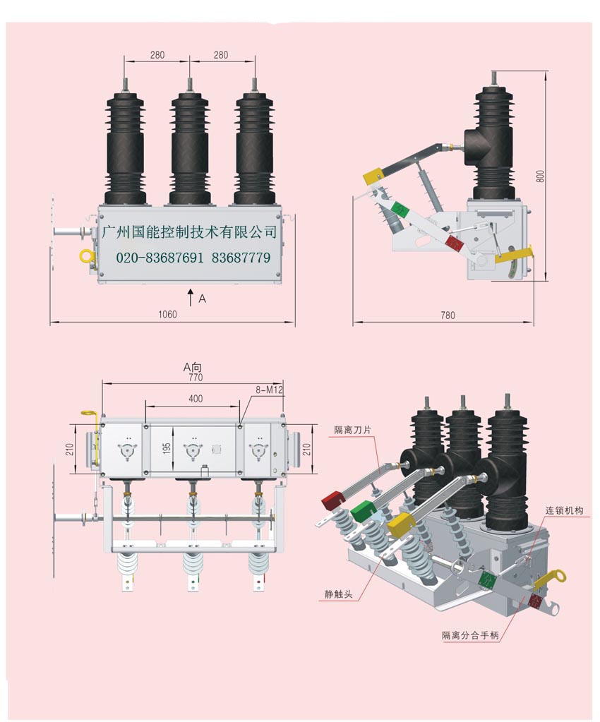
4.1对于需要加装隔离开关的用户,可选用NK3S-12G系列开关,外形尺寸及结构图见图一,图二。隔离开关用螺栓固定于NK3S-12断路器的机构箱上,坚固、稳定、拆卸方便、可靠,可灵活加装。
4.2隔离开关主要技术参数见表3
|
序号
|
项 目
|
单位
|
参数
|
|
1
|
额定电压
|
kV
|
12
|
|
2
|
额定电流
|
A
|
630/1250
|
|
3
|
4s额定短时耐受电流(有效值)
|
kA
|
16、20/31.5
|
|
4
|
额定峰值耐受电流
|
40、50/80
|
|
5
|
1min工频耐受电压
|
对地、相间
|
kV
|
42
|
|
断口
|
48
|
|
6
|
回路电阻(断路器接线板至隔离开关进线板间)
|
µΩ
|
≤100
|
|
7
|
三相刀闸合闸时中心偏摆量
|
mm
|
≤2
|
|
8
|
三相刀闸分、合闸同期性偏差
|
≤2
|
|
9
|
导电部分对地绝缘距离
|
≥160
|
|
10
|
断口开距
|
≥200
|
|
11
|
重量
|
kg
|
≤40
|
4.3隔离开关结构特点
隔离开关由隔离架12、绝缘子7、绝缘拉杆11、刀片10、隔离主轴2、进线板9、操作手柄1、电流互感器8等组成。隔离支架固定在机构箱上,利用断路器的接线端作为闸刀的支点,构成隔离断口的一端,断口的另一端通过操作绝缘子和驱动轴打开、关合刀闸。三相联动,在隔离开关分闸状态下有明显的可见断口,并具备与断路器本体之间的可靠防误机构联锁,维护方便,安全。
4.4隔离开关操作顺序
4.4.1合闸操作(送电操作)
a)拉动隔离开关操作手柄,闭合隔离刀,闭合到位;
b)拉动断路器储能手柄(电动机构即合闸);
c)拉下断路器合闸拉环,断路器合闸(电动机构时无此步)。
4.4.2分闸操作(手动断电、检修操作)
a)拉下断路器分闸拉环,断路器分闸;
b)断路器出线侧验电,确认无电。
c)拉动隔离开关操作手柄,打开隔离刀,打开到位。
4.4.3注意事项
a)严禁在断路器合闸时,分合隔离开关;
b)隔离开关必须分合到位,否则断路器不得进行分合闸操作。
c) 手动分闸前必须确认断路器出线侧无电。
5.运输、调试和安装
5.1产品在运输过程中不得翻转、倒置,并要采取防震措施。起吊断路器时,必须勾住箱体上的四个耳环吊起。不得直接搬运环氧绝缘套筒。
5.2开箱后应检查柱上断路器户外环氧绝缘套筒有无破裂,箱体是否变形,分合指示是否齐全,产品铭牌、合格证是否与订货单相符,装箱清单是否与实物相符。
5.3柱上断路器投入运行前,应仔细核对各操作元件的额定电压、额定电流与实际情况是否相符。
5.4断路器的触头参数和机械特性参数在出厂检验时就已经调整好,用户不必开箱检查。按要求进行耐压试验后,即可安装。有条件可以按照表2的要求进行机械特性检查。
5.5断路器可以单杆架设,也可以双杆架设。断路器应平稳、牢固地安装在专用钢架上使用(如图三所示)
安装前的准备工作:
1金具加工
依据选定的安装方式加工安装金具及外置PT支架,安装金具详细加工尺寸附件图。
2准备安装附件
以下是单台设备所需的附件数量:
1)高压避雷器6个(电源侧和负荷侧各3个)
2)10KV绝缘子(规格和数量依据安装方式和电杆的大小而定);
3)抱箍(规格和数量依据安装方式和电杆的大小而定);
4)开关出线连接线夹6个(具体尺寸依据现场线路的线径而定);
5)接地导线。
6)PT支架。
3待装设备检查
外观检查内容:
1)紧固和密封是否完好?
2)套管和壳体有无损伤?
3)控制插座及插针是否完好?
4)操作手柄及分合指针是否在正常位置?
绝缘测定内容:
1)绝缘电阻:一次对二次及地:≥10000MQ;二次对地:≥10MQ
2)绝缘耐压:一次对二次及地:42KV,1min;二次对地:2KV,1min;
安装步骤
第一步:安装断路器支架,及安装PT支架。
第二步:起吊
吊装前将开关置于分闸位置;
注意事项:
*钩挂在勾钩上的线绳长度应为0.8m;
*起吊过程中注意保护开关不要发生碰撞以免伤外壳和套管;
*开关允许稍有倾斜。
第三步:固定
把断路器起吊至比安装架水平横担略高位置后,将断路器放置在安装架水平横担上,并用四组M12x60的不锈钢螺栓螺母紧固。确认固定完好后,解开起吊线绳。
将外置式PT置于断路器下部PT安装架上,用4组M14x40的不锈钢螺栓,螺母紧固。
第四步:一次电缆的连接
1)当一次线路不需要安装隔离刀闸时,可直接用线夹将断路器两侧出线与线路相连接,如果一次线路需要安装隔离刀闸,则使用铜端子将线路与隔离刀闸出线侧相连。
2)用两根约10平方以上绝缘高压导线一头接在电源侧的AB相,另一头并接在PT的高压侧接线端子上.
注意事项:
*注意各相电缆之间的绝缘间距保持至少100mm以上;
*断路器离地面不小于6.5米 *PT与断路器的间距不小于1.5米
*请务必在开关每一相的两侧安装避雷器以防雷击对设备的损坏。
*如有控制器离地面不小于2.5米
6.产品的检修与维护
6.1本柱上断路器因其特殊的设计结构确保用户地使用中长期免维护,只需每隔三年左右进行一次工频耐压试验。
6.2用户不得随意更换使用与原型号规格不一致的电器元件。
6.3操作人员应初步了解机构的性能及安装调整、维护知识,对运行中问题应予以记录,必要时可通知制造厂家。
7.随机文件
7.1产品合格证一份。
7.2安装使用说明书一份。
7.3装箱单一份。
7.4出厂检验报告一份。
8.订货须知
订货时要说明产品的型号、名称、数量、额定电流、额定开断电流、所配电流互感器电流比、操作方式及操作电压等。
9.注意事项
9.1 严禁将直流屏电源极性及储能电容性接反,或将分合闸线圈输出端直接短接或与操作电源正、负极连接,否则会使控制器损毁,一切后果自行负责。
9.2 严禁使用控制器的输出电源为其他电设备供电。
9.3 控制器连线必须可靠,尤其是合分闸线圈引线,否则容易起弧损坏控制器。
9.4配储能电容使用时,AC220V电源输入必须串接限流电阻或电抗器为电容充电。
9.5 直接使用直流屏供电,将电源正负极与原储能电容的相应输入端直接连接。
9.6 控制器做长时间合分闸测试,建议每分种不超过三个合分。
9.7 本控制器是精密电子产品,严禁自行拆装,如有问题,返我公司处理。
9.8 随着技术进步及配电要求的改进和提高,今后说明书中有改进与不同之处,届时以改进后的内容为准,恕不另行通知。
|
供货日期
|
地点
|
|
工程名称
|
工程编号
|
|
产品名称
|
户外高压永磁柱上真空断路器
|
|
产品型号
|
NK3S-12 630A/1250A--20/31.5
|
|
额定电压
|
10KV
|
|
额定电流
|
630A/1250A
|
|
开断短路电流(4S)
|
20KA/31.5KA
|
|
关合短路电流(4S)
|
50KA/80KA
|
|
操作机构
|
永磁
|
|
PT数量
|
户外式1只 AC 220V / 50Hz
|
|
电流互感器变比
|
壳外式相CT400:5 (10P20),
|
|
开关外壳
|
不锈钢
|
|
PT与开关(2.5平方)电缆长度
|
7米
|
|
海拨高度
|
1km
|
|
控制器位置
|
内置
|
|
控制器功能
|
过流 速断 保护
|
|
通信方式
|
无
|
|
液晶遥控器
|
无
|
|
小遥控器
|
有
|
|
中性点接地方式
|
不接地
|
|
负荷侧容量
|
1250kVA
|
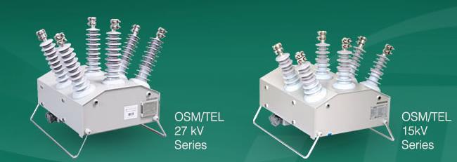
Intelligent use of our company's permanent magnetic phase controller, can also import switch matching other brands such as OSM ISM
The moving parts of OSM ISM monostable permanent magnetic actuator at all operating mechanism is less, and completely linear motion, so the wear of mechanical components is reduced to a minimum, the failure rate is reduced to the lowest. Mechanism of the center part has two piece of soft magnetic alloy material, can provide the contact pressure of more than 230kg. Closing position, contact pressure on the closed magnetic circuit will generate institutions remain in the closing position, the yoke will seal in the middle of a single coil, coil to provide energy for the mechanism of operation.
(1) the closing operation
In the off position, the moving contact of vacuum interrupter by separating brake spring is connected with the driving insulator remain in the off position. The need to implement the closing operation, control of switching capacitor module into a pulse current to the agency within the coil, when the static contact, a moving contact stops moving, but moving core to continue to exercise 2mm, a pressure spring compression contact. Between the movable core and yoke to realize locking through the magnetic coil current, then further increases, the flux of magnetic material saturated. Therefore, cut off the control coil current module sends in the closing position, the movable iron core saturation flux to keep in close position. At the same time the moving iron core that the separating spring energy storage, ready for the next gate operation.
(2) opening operation
Break brake operations, control gate capacitor module to institutions coil into a reverse pulse current, time is 15~20ms. The current on the magnetic material center produces part of demagnetizing effect, reduces the closing retention, the opening spring and the contact pressure spring reverse force now energy storage of the movable iron core release, to the open direction of accelerated motion, ultimately rely on separating spring remain in the off position.
As shown in Figure 3, the ISM type monostable permanent magnetic actuator of vacuum circuit breaker all switch element axial symmetric arrangement, are straight line motion, saves the motor, gear, a connecting rod, a chain and a mechanical lock parts.
Failure statistics for the vacuum circuit breaker analysis showed that the circuit breaker fault 75% for mechanical fault. The use of independent agencies three-phase is monostable permanent magnetic mechanism of a circuit breaker main advantage, mechanism and a vacuum arc extinguishing chamber most mechanical connection between the element was removed and the only one moving part left, compared with the traditional circuit breaker at least hundreds of moving parts, it almost completely eliminates the possibility of the generation of mechanical faults. ISM entered the Chinese market in recent years, the permanent magnetic actuator of circuit breaker monostable China operation has reached thousands of Taiwan, did not happen with a mechanical or electrical failure.
While the majority of bistable permanent magnetic actuator of vacuum circuit breaker and traditional vacuum circuit breaker, by a mechanism operating three-phase switch, must use the transmission parts; in the arrangement of the elements only by permanent magnetic mechanism instead of the spring mechanism, a crank arm connecting rod transmission mechanism did not cancel, not be completely linear motion generation therefore not fully eliminate the mechanical fault.
Electrical control
Any permanent magnetic mechanism needs a suitable electronic control unit, and its role is to provide appropriate energy for the mechanism and Realization of coil, anti jump, atresia and and switch equipment interface and other functions. As a part of the circuit breaker, the control unit also need high reliability design principle; selection of components, especially switching capacitor; manufacturing principles; ensure the quality of several aspects of software testing. Among them, the sub gate capacitor and switching capacitor as the energy storage element is the most important, its life is mainly affected by temperature. In addition, low power design of circuit breaker is also guaranteed a factor capacitor longevity, monostable permanent magnetic mechanism of a circuit breaker control module into the exercise maximum switching current peak actuator coil only 10A (20kA type), 17A (31.5kA type), gate current is only 1A.
Vacuum 3.2 monostable permanent magnetic mechanism for circuit breaker interrupter technique
Due to the high reliability, long service life and is suitable for frequent operation of permanent magnetic actuator match, improved performance of vacuum arc extinguishing chamber is very urgent. Not only need to improve their fault current breaking capacity, but also needs to improve its reliability in load current. Sealing breakthrough performance in two areas to achieve improvements in the design and the contact system of vacuum type ISM monostable permanent magnetic mechanism of a circuit breaker arc extinguish chamber properties make it completely and its operating mechanism in the reliability and the service life of the match.
Figure 4 in vacuum interrupter using longitudinal magnetic field to get the cathode spots distribution optimization
Longitudinal magnetic field can improve the distribution of vacuum arc in condition of contact surface, reduce the ablation extent in the contact arc. Vacuum arc can be regarded as the discharge phenomenon has tremendous energy, it will contact surface loss serious, only makes the arc quickly and evenly distributed in the contact surface, the current density of each point on the surface of the contact to a minimum, in order to maximize the performance of the vacuum interrupter contact system.
(1) high current vacuum arc under uniform longitudinal magnetic field
In 1967, Ito and Okura first proposed a longitudinal magnetic field in control applications on high current vacuum arc, found in the experiment, by vacuum magnetic field distribution of longitudinal breaking capacity can significantly increase (increased about 50%~100%).
Further research showed that the longitudinal magnetic field controlling arc depends on the strength of the magnetic field. If the magnetic field is too weak, the cathode spot is not stable, level surface even from the contact; but when the magnetic field is too strong, the cathode spot is not distributed throughout the contact surface; only when the magnetic field intensity reaches a certain value for the interval, the cathode spot can be distributed over the whole surface of contact. Figure 4 shows the Reed researchers in the vacuum interrupter using longitudinal magnetic field to get the cathode spots distribution diagram optimization.
(2) non uniformly high current vacuum arc under longitudinal magnetic field
Commercial vacuum interrupter has been devoted to the study of inhomogeneous longitudinal magnetic field. For the first time and longitudinal magnetic field is applied to the vacuum interrupter products in twentieth Century 70's.. 80 in the early discovery of inhomogeneous longitudinal magnetic field on vacuum arc effect. A large number of experiments with different magnetic field structure of the display, in particular the electric current and the magnetic field structure, whether magnetic field, the cathode spot will move. The study found that the contact edge part has a strong magnetic field is similar to magnetic barrier, magnetic field structure of contact center area of the weakest is the magnetic field structure optimization, by measuring the contact of cathode current density and proved. In addition, in the center of the electrode does not need to limit the longitudinal magnetic field and stable arc cathode spots.
(3) vacuum with longitudinal magnetic field structure and the optimal contact materials arc quenching chamber
To the above research results are applied to the vacuum interrupter products, also need to do a lot of work, including the determination of the contact shape, the best selection of the most suitable contact materials etc.. Contact structure shape can determine the longitudinal magnetic field, and therefore decides the distribution of arc. Contact materials should also satisfy the vacuum arc extinguishing electrical performance of demanding chamber and the mechanical performance requirements. For example, contact materials should have very strong anti welding properties, so it needs to have good conductivity and lower welding mechanical strength; non electrical contact materials and requirements of performance and has high (which to a large extent and mechanical strength related); still need it has good thermal conductivity, conductivity in order to provide high breaking capacity. Information please visit: equipment for power transmission and distribution network
Tyd through the study found that different material matched with special alloy material produced can meet the above requirements. This kind of alloy contact production by vacuum arc extinguish chamber in the rated current of the breaking times it is easy to reach more than 100000 times to 100 times, breaking at rated short circuit current.
(4) vacuum metal bellows seal performance is improved through innovative design and technology
In addition to contact system, the sealing performance of metal corrugated pipe is another important factor in determining if the service life of the vacuum interrupter. Metal corrugated pipe by the traditional stainless steel stamping, as shown in Figure 5 (a), in the arc quenching chamber division process, high plus
Speed will produce the enormous pressure on the corrugated pipe, corrugated pipe caused by fatigue is the main reason for the current leakage of the vacuum interrupter fault.
Corrugated used ISM monostable permanent magnetic vacuum circuit breaker pipe is composed of a group of stainless steel ring plate in the medial and lateral alternately welded. The corrugated pipe with the design in mechanical close operation in the process of stress is distributed uniformly on the whole ring piece, a single point of the pressure is greatly reduced, as shown in Figure 5 (B). The application of this technology, not only the vacuum arc extinguishing chamber to realize compact appearance, but also the mechanical service life can reach 150000 times the rated.
使用我公司的智能永磁分相控制器,还可以选配其他品牌的进口开关例如OSM ISM
OSM ISM 单稳态永磁操动机构的运动部件在目前所有操动机构中比较少,而且完全直线运动,因此可将机械部件的磨损减到最小,故障率降到最低。机构的中心部分有两块软磁性合金材料,可提供超过230kg的触头压力。合闸位置时,依靠闭合磁路产生的触头压力将机构保持在合闸位置,磁轭将单线圈封在中间,线圈为机构操作提供能源。
(1)合闸操作
在分闸位置,真空灭弧室的动触头由与驱动绝缘子连接的分闸弹簧保持在分闸位置。需要实行合闸操作时,控制模块内的合闸电容器向机构线圈内注入一个脉冲电流,当动静触头接触后,动触头停止运动,但动铁心继续运动2mm,压缩触头的压力弹簧。动铁心和磁轭之间通过磁力实现锁扣,这时线圈电流进一步增大,磁性材料的磁通达到饱和状态。因此,在合闸位置切断控制模块发出的线圈电流时,此饱和磁通使动铁心保持在合闸位置。动铁心运动的同时使分闸弹簧储能,为下次分闸操作做好准备。
(2)分闸操作
分闸操作时,控制模块内的分闸电容器向机构线圈注入一个反向脉冲电流,时间为15~20ms。该电流对机构中心的磁性材料产生部分消磁作用,减小了合闸保持力,这时已储能的分闸弹簧和触头压力弹簧的反向力使动铁心释放,向分闸方向加速运动,最终靠分闸弹簧保持在分闸位置。
如图3所示,ISM型单稳态永磁操动机构真空断路器的所有开关元件轴向对称布置,均为直线运动,省掉了电机、齿轮、连杆、链条和机械锁扣等零件。
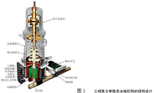
对真空断路器的故障统计分析显示:75%的断路器故障为机械故障。三相独立机构的使用是单稳态永磁机构断路器最主要的优点,机构和真空灭弧室之间的大部分机械连接元件被去掉了,只剩下一个活动部件,相对于传统断路器至少有上百个活动零部件来说,它几乎完全消除了产生机械故障的可能性。ISM进入中国市场几年来,在中国运行的单稳态永磁机构断路器已达到数千台,未发生过一例机械或电气故障。
而多数双稳态永磁操动机构真空断路器与传统真空断路器一样,由一个机构操动三相开关,必须使用传动件;在元件布置上只是用永磁机构代替了弹簧机构,拐臂连杆等传动机构并没有取消,无法实现完全直线运动,因此不能全面消除机械故障的产生。
电气控制
任何永磁机构都需要一个合适的电子控制单元,其作用是为机构线圈提供合适能量,并实现防跳、闭锁以及与开关设备的接口等功能。作为断路器的一部分,控制单元同样需要高可靠性,设计原则;精选元件,尤其是分合闸电容器;制造原则;软件测试等几方面保证其质量。其中,分闸电容器与合闸电容器作为储能元件是最重要的,其寿命主要受温度影响。另外,断路器的低能耗设计也是保证电容器长寿命的一个因素,单稳态永磁机构断路器控制模块注入到操动机构线圈的最大合闸电流峰值只有10A(20kA型)、17A(31.5kA型),分闸电流只有1A。
3.2 单稳态永磁机构断路器的真空灭弧室技术
由于要与可靠性高、寿命长并适于频繁操作的永磁操动机构相匹配,真空灭弧室性能的改进显得非常迫切。既需要提高其对故障电流的开断能力,又需要改善其在负荷电流下的可靠性。ISM型单稳态永磁机构断路器的真空灭弧室在触头系统设计和密封性能两方面实现的突破性改进,使其在可靠性和使用寿命上完全与其操动机构的性能相匹配。
图4 在真空灭弧室中利用纵磁场得到最优化的阴极斑点分布
纵磁场能改善真空电弧在触头表面的分布状况,减轻触头在电弧下的烧蚀程度。真空电弧可被视为具有巨大能量的放电现象,它能将触头表面严重烧损,只有使电弧迅速而均匀地分布在触头表面,将触头表面上每个点的电流密度降至最低,才能最大程度地提高真空灭弧室触头系统的性能。
(1)均匀纵磁场下的大电流真空电弧
1967年,Ito和Okura第一次提出了关于纵磁场在控制大电流真空电弧上的应用,试验中发现,采用纵磁场分布的真空灭弧室的开断能力能够显著提高(约提高50%~100%)。
更多的研究显示,纵磁场控制电弧的能力依赖于磁场的强度。如果磁场太弱,阴极斑点不稳定,甚至会脱离触头的水平表面;但磁场太强时,阴极斑点则不能分布于整个触头表面;只有当对于磁场强度达到一定区间值时,阴极斑点才能分布于整个触头表面。图4所示为特瑞德的研究人员在真空灭弧室中利用纵磁场得到最优化的阴极斑点分布示意图。
(2)非均匀纵磁场下的大电流真空电弧
商业用真空灭弧室一直致力于非均匀纵磁场的研究。首次将纵磁场应用于真空灭弧室产品是在20世纪70年代。80年代初期发现了非均匀纵磁场对真空电弧的影响。大量对不同磁场结构的试验显示,在特定电流和磁场结构下,无论磁场强弱,阴极斑点都会移动。研究发现,触头边缘部位具有类似磁屏障的强磁场,触头中心区域强度最弱的磁场结构是最优化的磁场结构,通过测量触头阴极电流密度而得到证明。此外,在电极的中心区域不需要纵磁场来限制阴极斑点及稳定电弧。
(3)具有纵磁场结构和最佳触头材料的真空灭弧室
要将上述研究成果应用到真空灭弧室产品中,还需要做许多工作,包括确定最佳的触头形状、选择最适合的触头材料等。触头形状能决定纵磁场的结构,并因此决定电弧的分布。触头材料则要同时满足真空灭弧室苛刻的电气性能要求和机械性能要求。例如,触头材料应具有极强的抗熔焊性能,因此它需要具有良好的导电性能和较低的熔焊机械强度;同时又要求触头材料具有较高的非电气性能(这一点在很大程度上与机械强度相关);还需要它具有良好的导热、导电性能以提供高开断能力。 信息请登陆:输配电设备网
特瑞德通过研究发现,几种不同材料相配合产生的特殊合金材料可满足以上要求。利用这种合金触头生产的真空灭弧室,在额定电流下的开断次数很容易达到10万次以上,在额定短路电流下能开断100次。
(4)通过创新设计和工艺提高金属波纹管的真空密封性能
除触头系统以外,金属波纹管的密封性能是决定真空灭弧室寿命的另一个重要因素。传统的金属波纹管由不锈钢冲压而成,如图5(a)所示,在灭弧室的分合过程中,极高的加
速度会对波纹管产生巨大压力,波纹管因疲劳产生漏气是目前真空灭弧室故障的主要原因。
ISM单稳态永磁真空断路器所用的波纹管由一组不锈钢环片在内侧和外侧交替焊接而成。采用这种设计的波纹管,在分合操作过程中机械应力均匀分布到整个环片上,单点受到的压力大大减小,如图5(b)所示。这项技术的应用,不仅使真空灭弧室实现外型小巧,而且其额定机械寿命可达到15万次。