1. Overview of NK3S Intelligent Permanent Magnet Circuit Breaker Products--Single-phase Independent Permanent Magnet Mechanism Drive
1.1 Main uses
NK3S outdoor high-voltage permanent magnet vacuum circuit breaker (hereinafter referred to as circuit breaker) is the outdoor distribution equipment with the highest rated voltage of 12/24kV/35kV/38kV/40.5KV and 50Hz single-phase AC. It is mainly used for breaking and closing the load current, overload current and short circuit current in power system. It is suitable for protection and control in power distribution system of substation and industrial and mining enterprises. It is more suitable for rural power grid and frequently operated places, especially for urban power network and rural power network transformation.
The installation instructions specify the main technical parameters, product structure, principles and methods of operation, installation, use and maintenance of circuit breakers.
1.2 Reference Standards
GB1984-2003 AC High Voltage Circuit Breaker
GB/T 1022-1999 Common Technical Requirements for Standards of High Voltage Switchgear and Control Equipment
GB311.1-1997 Insulation Coordination of High Voltage Transmission and Transformer Equipment: High Voltage Test Technology
GB3309-1989 Mechanical Test of High Voltage Switchgear at Room Temperature
DL/T403-2000 Technical Conditions for Order of 12-40.5 kV High Voltage Vacuum Circuit Breakers
1.3 Environmental Conditions for Use
1.3.1The altitude does not exceed 2000 meters;
1.3.2 Ambient air temperature: - 45 ~40;
1.3.3 wind speed is not more than 35m/s;
1.3.4 Pollution Level: IV Level
1.3.5 Installation site: No flammable, explosive danger, chemical corrosion site.
1.3.6 Earthquake Intensity Not More than 8 Degrees
1.4 Main Characteristics
1.4.1 Fully sealed structure: good sealing performance, help to improve moisture-proof and condensation-proof performance, suitable for high temperature and humid areas, effectively avoid mechanical corrosion caused by long-term outdoor environment of switches.
1.4.2 circuit breaker adopts single-phase pillar structure, which has stable and reliable interruption performance, compact and reasonable overall structure, small size and light weight. Long service life and other characteristics.
1.4.3 Vacuum Arc Extinguishing Chamber: Interruption performance is stable and reliable, contact wear is small, no flammable and explosive danger, safe and maintenance-free.
1.4.4 Single-phase props and current transformers are insulated by high-quality outdoor silicone rubber solids. They are resistant to high and low temperatures, ultraviolet radiation and aging.
1.4.5 Circuit Breaker adopts permanent magnet operating mechanism, with less parts, small size, maintenance-free, and mechanical life of more than 30,000 times. The operation mechanism is placed in the sealed shell, which solves the problem of mechanism Corrosion and improves the reliability and service life of the mechanism.
The opening operation of 1.4.6 circuit breaker can adopt manual and electric opening and closing operation and provide remote operation interface. Distribution automation can be realized with the controller, and a watchdog circuit breaker or recloser can be formed with the demarcation controller.
1.4.7 The ABC phase of circuit breaker is equipped with current transformers and outdoor voltage transformers, which are used for over-current automatic trip protection and information analysis with intelligent controller to realize various protection functions.
1.5 Product Model
NK3S-12G 630A/1250A-20/31.5
20/31.5 rated short circuit interruption current (kA)
630/1250 rated current (A)
G disconnector
12/24/35KV/38KV/40.5 Maximum Working Voltage (KV)
NK3S Design Serial Number Three-phase Independent Permanent Magnet Mechanism Drive
2. Technical parameters
2.1 The main technical parameters are shown in Table 1.
2.2 The mechanical properties are shown in Table 2.
2.3 The characteristics of the operating mechanism are shown in Table 3.
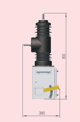
2.4 The outline and installation dimensions of circuit breakers are shown in Fig. 1, Fig. 2, Fig. 3 and Fig. 4.
3. Operating mechanism and its action principle
3.1 Action principle of manual mechanism.
Table 1 breaker data
|
REF
|
PROJECT
|
UNIT
|
VALUE
|
|
1
|
Rate Voltage
|
kV
|
12
|
|
2
|
Rated frequency
|
Hz
|
50
|
|
3
|
Rated frequency
|
A
|
630/(1250)
|
|
4
|
Rated short circuit breaking current
|
kA
|
20/(31.5)
|
|
5
|
Rated peak tolerance current (peak)
|
kA
|
50/(80)
|
|
6
|
Rated short circuit withstand current/duration
|
kA/s
|
20/4 /(31.5/4)
|
|
7
|
Rated short circuit closing current (peak value)
|
kA
|
80
|
|
8
|
Rated operation sequence
|
|
O-0.3s-C-O-180s-C-O
|
|
9
|
Mechanical life
|
次
|
10000
|
|
10
|
Mechanical life
|
次
|
10000
|
|
11
|
Rated number of short circuit breaking current breaking times
|
次
|
30
|
|
12
|
50HZ withstand voltage (1min):
(wet) facing the ground
(dry) alternating, ground-to-ground/fracture
|
kV
|
34
42/49
|
|
13
|
Lightning Shock Tolerance Voltage (Peak) Interphase, Ground to Ground/Fracture
|
kV
|
75/85
|
|
14
|
Power 50HZ Voltage Withstand of Secondary Circuit for 1 Min
|
V
|
2000
|
Table 2 the main mechanical characteristics of circuit breaker
|
REF
|
PROJECT
|
UNIT
|
VALUE
|
|
1
|
Contact opening distance
|
mm
|
11±1
|
|
2
|
Contact overrun
|
mm
|
3±0.5
|
|
3
|
Average closing speed
|
m/s
|
0.6±0.2
|
|
4
|
Average Opening Speed
|
m/s
|
1.0~1.4
|
|
5
|
Contact closing bounce time
|
ms
|
≤2
|
|
6
|
Interphase Center Distance
|
mm
|
280±2
|
|
7
|
Different Periods of Three-Phase Shut-in and Shut-in
|
ms
|
≤2
|
|
8
|
Resistance of each phase conductive circuit
|
µΩ
|
≤80
|
|
9
|
Closing time
|
ms
|
30~50
|
|
10
|
Opening time
|
ms
|
30~70
|
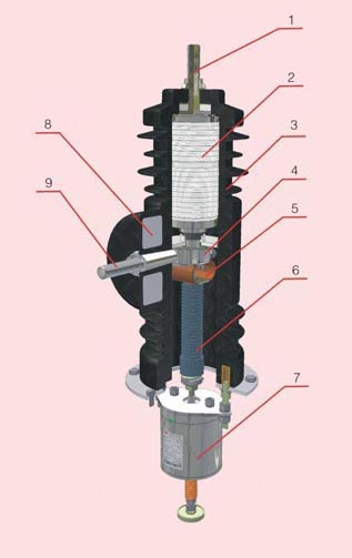
1 upper conductive rod
2 vacuum interrupter
3 insulating cylinder
4 conductive clamp
5 soft links
6 insulated tie rod
7 permanent magnet mechanism
8 Current Transformer
9 lower conductive pole