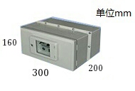
NKY300 Dimensions: 300 × 200 × 160 Unit: mm
Figure 2: Switch and controller installation diagram
NKY300 permanent magnet switch controller, built-in capacitor / 24V to 300V booster board / permanent magnet mechanism drive board, mainly should
Various permanent magnet vacuum contactors, circuit breakers, reclosers, and mines for use in 10KV, 35KV distribution lines
In the vacuum circuit breaker, the closing and opening process of the permanent magnet switch is controlled.
Dimensions are 300* wide 200mm high 160mm high and weigh 1kg
Second, the model description NKY-300 single coil (single bistable), double coil (single bistable) can be used by users
Requires customization of various special features.
Third, the main features
Structural principle
of an external DC DC24V1A (maximum 24V2A) to the boost power supply board, 40w booster plate boosted to 300V to 24V to the electric capacitance charge
After receiving the 24V (1A or lower) opening or closing signal, the driver board outputs 300V 20ms DC pulse to the permanent magnet.
Mechanism coil
Features 1,
1us high-speed start, from the input signal trigger to the capacitor output energy to the coil 1us.
2. Timing output 20ms pulse, after a single signal input, output a timing 300V 20ms pulse to the coil.
.
3, short circuit protection against blocking, built-in detection of current components, when the coil current is greater than 500A, stop within 3us
Out
4. The PWM starts and shuts down, which can effectively protect the control components.
5, over voltage feedback charging, can effectively prevent over voltage.
6, high efficiency charge and discharge control, low capacitance of capacitors, can meet the requirements of switch coincidence.
7, adjustable output power, can adjust the output voltage by adjusting the W503 of the booster board to achieve the adjustment mechanism
The purpose of the effort.
8. The closing and closing signal input interlocks the anti-double-pass, and the closing and closing signal input is forbidden to input at the same time, otherwise the signal is burned out.
Input.
Wiring instructions:
1. It is forbidden to load the opening signal and the closing signal at the same time.
2. DC24V power supply and signal pin can only input DC power supply, voltage range +-10%
(cannot input AC).
3, pay attention to the internal circuit of the controller has 300V, even after the 24V power supply and signal disconnection, the capacitor is still inside
There is 300V, please don't touch, pay attention to safety.

.jpg)